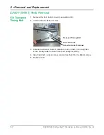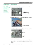
DA80F/DA95F AddressRight™ Printers Service Manual (SV61962 Rev. A)
5-3
Removal and Replacement • 5
3. Lift up to free the two tangs on the bottom of the cover from the slots in
the floor of the rear chassis assembly and remove the rear cover.
4. Disconnect the ribbon cable from the keyboard/LCD board (bottom left
figure) and green ground screw from frame (bottom right figure).
<-Two
Screws
for Rear
Cover
(Circled)
Rear ->
Cover
Removed
DA80F (WF81) Parts Removal
WARNING!
Always wear anti static wrist straps (L-8258) whenever handling the main
processor board or keyboard /LCD Board. Static discharge will damage
the IC chips.
1. Turn the power off and unplug the AC power cord. Remove extension
bins (two thumbscrews) and wireform media holder.
2. Unfasten the two screws securing the rear cover.
5.2 Rear
Cover and
Keyboard/
LCD Display
Board
6. Support the keyboard/LCD board from inside the rear chassis assembly,
then unfasten the three screws securing the keyboard/LCD board.
7. Reinstall in reverse order.
5. Remove the keyboard overlay from the top of the rear chassis assembly
to gain access to the screws beneath.
Ribbon Cable
Green
Ground
Cable
Keyboard/LCD Board
Keyboard
Overlay
Screws Under
Overlay (dotted
circles)


