


SitG Electricity User Guide ROI V1017
5
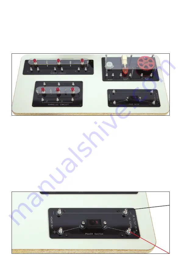
STEM in the Gym Electricity Demo Board
The demo board (Figure 3) can be powered by a battery pack that
consists of two 6-volt batteries in a plastic case. Alternatively, the
demo board can be powered by the STEM in the Gym Generator.
Instructions below assume that power is being supplied by the
battery pack.
Wiring the Power Switch
1. Make sure power switch is in the off position. Use a black lead to
connect the (-) terminal of first battery to the (-) terminal of the
second battery.
2. Using a red lead, connect the (+) terminal of the battery pack to
the (+) terminal of the power in side of the power switch area.
3. Using a black lead, connect the (-) terminal of the second battery
to the (-) terminal of the power in side of the power switch area
(Figure 4).
Figure 3
Figure 4


