background image

SitG Electricity User Guide ROI V1017
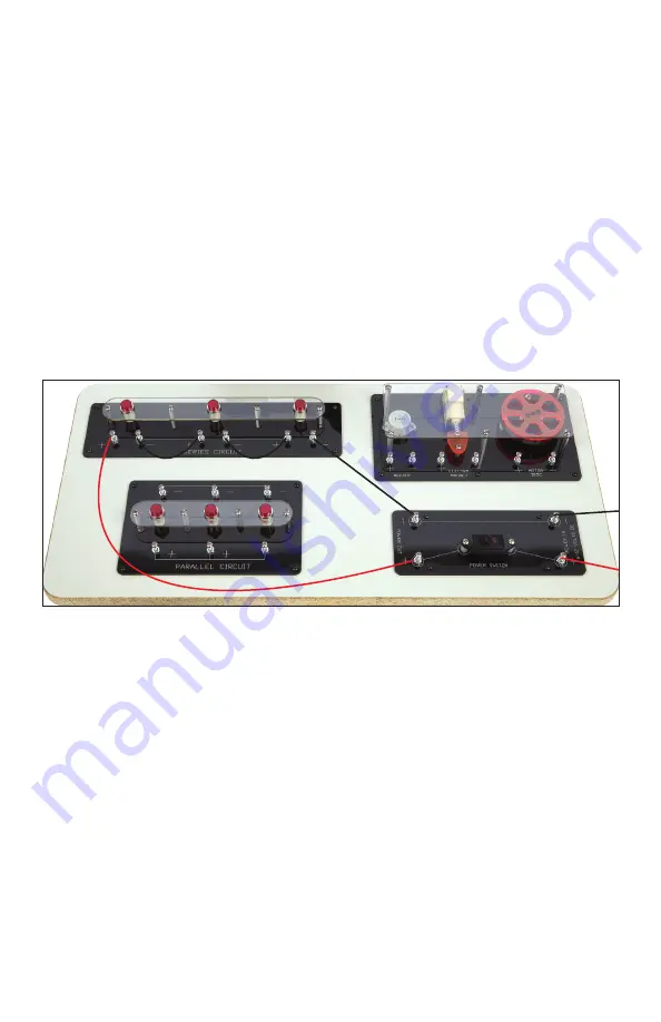
Series Circuit

1.  Using a red lead, connect the (+) terminal of the power out side 

of the power switch area to the (+) terminal on the left side of the 

series circuit area.  

2.  Using a black lead, connect the (-) terminal of the power out side 

of the power switch area to the (-) terminal on the right side of the 

series circuit area. 

3.  Turn the power switch on to observe that the circuit is not yet 

complete. The lights will not turn on. 

4.  Turn the switch off to continue making connections for the circuit. 
5.  Using two additional leads (color does not matter), finish making 

the circuit connections as shown in Figure 5. 

Parallel Circuit

1.  Using a red lead, connect the (+) terminal of the power out side of 

the power switch area to the (+) terminal on the right side of the 

parallel circuit area.  

2.  Using a black lead, connect the (-) terminal of the power out side 

of the power switch area to the (-) terminal on the right side of the 

parallel circuit area. 

3.  Turn the power switch on to observe that the first light comes on, 

but the other two lights do not.

4.  Turn the power switch off  to continue connecting the circuit.
5.  Use leads (black for the (-) terminals, red for the (+) terminals) to 

connect the other two lights within the parallel circuit area as 

shown in Figure 6.

Figure 5

Summary of Contents for STEM in the Gym Electricity

Page 1: ...ROI V1017 STEMintheGymTM Electricity UserGuide...

Page 2: ...ymTM Generator STEM in the Gym Generator 24 alligator clip leads 3 black and 3 red Battery Box Battery box 6 volt battery 2 STEM in the Gym Electricity Demo Board STEM in the Gym Demo Board 12 alligat...

Page 3: ...esponding terminals on the board you wish to power 3 To use the generator kneel on the pad in front of the generator and turn the cranks Figure 1 The faster you crank the more electricity you generate...

Page 4: ...ry box contains two 6 volt batteries When the battery box is used with the boards it is necessary to connect the batteries to complete the circuit 2 Connect a red lead to the terminal of one battery a...

Page 5: ...e that power is being supplied by the battery pack Wiring the Power Switch 1 Make sure power switch is in the off position Use a black lead to connect the terminal of first battery to the terminal of...

Page 6: ...o additional leads color does not matter finish making the circuit connections as shown in Figure 5 Parallel Circuit 1 Using a red lead connect the terminal of the power out side of the power switch a...

Page 7: ...t side of the power switch area to the terminal of the buzzer 2 Use a black lead to connect the terminal of the power out side of the power switch to the terminal of the buzzer Figure 7 3 Turn the swi...

Page 8: ...will use the black lead For these instructions you will wire the knife switch to the light and buzzer board 1 Make sure the knife switch is open Use a black lead to connect the terminal of the batter...

Reviews: