AM2020/AFP1010 Troubleshooting Guide 50432 Revision A 8/13/97
5
Section Two:
AM2020/AFP1010 Hardware
A Ground Fault is an unintentional connection of one or more system conductors
(wires, equipment electronics, etc.) to some object which is electrically tied to
earth ground. This connection may be direct contact, capacitive coupling,
inductive coupling, or any combination of these things.
Note: The sensitivity threshold of the ground fault detection circuit on the MPS-24A Power
Supply is approximately 50,000 ohms. Any single or combined impedance to ground
within the AM2020/AFP1010 system using this supply having less than
50,000 ohms will cause a ground fault.
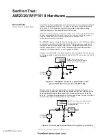
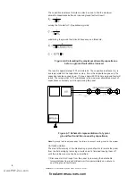
The MPS-24A uses a 1/4 Hertz, 4.0 Vpp square wave on a 2.0 VDC bias relative
to system common for ground fault detection. This square wave is present on
the cabinet and is referenced to earth ground. A simplified schematic of this
circuit is shown below. Point "a" on the schematic represents the electrical
location of the cabinet which is at earth ground potential.
During a normal condition, the pulse detection circuitry detects the square wave
at the proper peak-to-peak potential (4.0 Vpp) at Point "b" and no ground fault is
indicated.
Figure 2-1: Simplified schematic representation of the
ground fault detection circuit on the MPS-24A
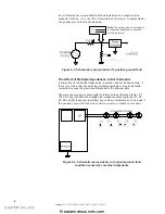
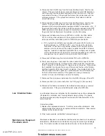
When a conductor from the panel (either a system common conductor or a
voltage carrying conductor) has some low impedance path to earth ground, the
peak-to-peak amplitude of the square wave is reduced and a ground fault is
detected. A schematic representation of what happens when a system common
conductor is faulted to earth ground is shown below.
Figure 2-2: Schematic representation of a negative ground fault
Note: The square wave is
detected at the proper amplitude
so no ground fault is indicated.
Note: The square wave is detected at
an improper amplitude so a ground
fault is indicated.
Ground Fault.
(Also referred to as Earth Fault)
www.PDF-Zoo.com
firealarmresources.com


