AM2020/AFP1010 Troubleshooting Guide 50432 Revision A 8/13/97
7
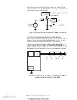
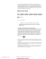
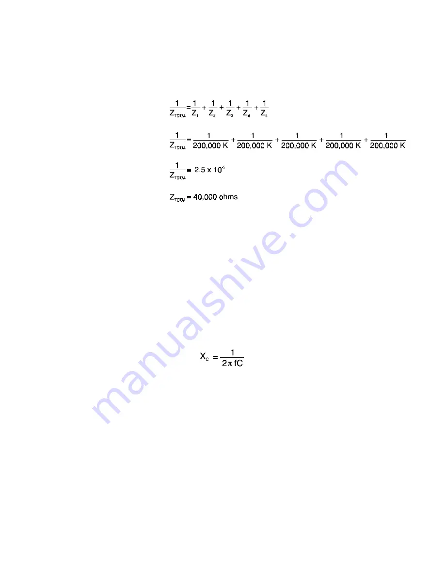
For the sake of this example, let's assume that each of these impedances to
earth is approximately 200,000 ohms. Since all these impedances have found a
path to earth ground at Points "b","c","d","e", and "f" which are electrically
effectively the same point as Point "a", all these impedances can be considered
to be in parallel. Based on the simple calculations shown, we can see how the
ground fault threshold is indeed exceeded.
Note: Since Z
TOTAL
is less than 50,000 ohms, a ground fault will result.
Figure 2-5: Calculating the parallel impedances of multiple
ground faults
The Affects of Capacitance on Ground Faults
Capacitance can also be a major cause of induced ground faults. For example,
if the capacitance between the conductors of an SLC loop and earth ground
exceed a certain value, the capacitive reactance (X
C
) will fall below the ground
fault circuit threshold and a ground fault indication will result. When using
shielded cable for the SLC loop wiring, it is important to realize that since a
conductor (the SLC loop wire) is running in close proximity to the shield for a
long distance, it is basically acting as a large capacitor. If the capacitive value is
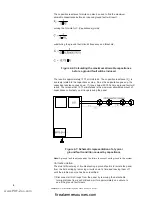
known, the capacitive reactance can be calculated by using the following
formula;
Where "f" is the frequency (in Hertz) of the ground fault detection circuit, in this
case one-quarter hertz (0.25 Hz) and "C" is the measured capacitance value (in
Microfarads).
Example: If the measured capacitance value is 10 microfarads, the capacitive reactance
will be approximately 63,660 ohms. Since this value does not drop below the threshold of
50,000 ohms, no ground fault will result.
Example: If the measured capacitance value is 15 microfarads, the capacitive reactance
will be approximately 42,441 ohms. Since this value is below the threshold of 50,000
ohms, the result will be a ground fault indication.
www.PDF-Zoo.com
firealarmresources.com


