background image


Attach the end of the delivery to the slot provided on the tank 


Turn the ON/OFF switch to the OFF position. 

 
Resume the oil cleaning operations after determining the cause of the 
stop.


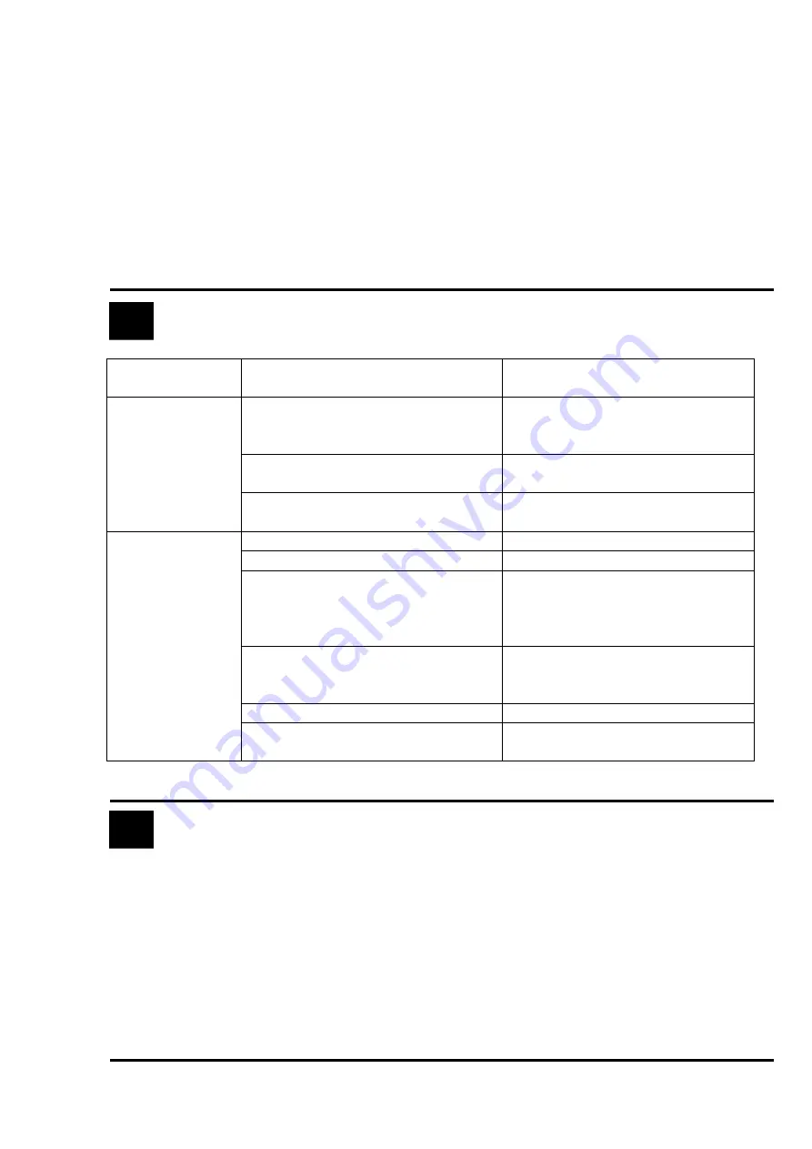
PROBLEMS AND SOLUTIONS


PROBLEM 

CAUSE 

SOLUTION 
 

Lack of electric power 

Check the electrical 
connections and the safety 
systems. 

Pump rotor blocked 

Dismount the pump body and 
check. 

Motor not 
turning 

Motor problems 

Contact the Service 
Department 

Foot valve blocked 

Clean or replace 

Filter clogged 

Replace the filter 

Excessive suction pressure 

Reduce the difference in 
height between the 
DEPUROIL and the suction 
tank 

Low rotation speed 

Check the voltage at the 
pump.  
Adjust voltage if insufficient. 

Fluid leaking 

Check connections and seals. 

Low or no 
flow rate 

Air entering the pump or the 
suction tubing 

Check connections and seals. 


MAINTENANCE


Check the pump body and tubing joints on a regular basis to 
promptly reveal any leaks. 


Keep the pump body always clean to avoid wearing the rotating parts 
due to the presence of undischarged solid particles.  


During use check the pressure detected by the pressure gauge 
installed on the filter cover and replace the filter when clogged.


Check that the electric power supply cables are in good condition. 


Summary of Contents for DEPUROIL

Page 1: ...O EXPLODED DIAGRAMS AND SPARE PARTS G HANDLING AND TRANSPORT B MACHINE AND MANUFACTURER IDENTIFICATION MODEL DEPUROIL DEPUROIL DEPUROIL DEPUROIL MANUFACTURER PIUSI S p A ITALIA PLATE Always check that the revision level of this manual coincides with what is shown on the identification plate USE AND MAINTENANCE MANUAL V M 0047 REV A DEPUR OIL DEPUR OIL DEPUR OIL DEPUR OIL CE MARK Production year Mo...

Page 2: ...chnical Principles EN 294 Safety of Machinery Safe Distances to Prevent the Operator s Upper Limbs from Reaching Dangerous Areas EN 50081 1 Electro Magnetic Compatibility Generic Emission Standards Residential Commercial and Light Industrial Environments EN 50082 1 Electro Magnetic Compatibility Generic Emission Standards Industrial Environments EN 55014 Limits and Methods for Measuring Radio Dist...

Page 3: ...ades of Protection for the Housings of Rotating Electrical Machinery NATIONAL REGULATIONS DPR 547 55 Regulations for the Prevention of Accidents in the Workplace Suzzara 31 01 00 Otto Varini Otto Varini Otto Varini Otto Varini President ...

Page 4: ...rile rubber seals An extra screw type cartridge is available Delivery tube PVC spiral tube diameter 20 mm length 2 5 m connected with the filter outlet by means of the hose holder It includes an aluminum tube 0 5 m long at its end Suction tube PVC spiral tube with diameter 20 mm length 2 m connected to the pump inlet by means of the hose holder It includes a metal wire filter at the end E ELECTRIC...

Page 5: ...mal operating conditions they can function continuously with no limitations F4 FLUIDS PERMITTED OIL VISCOSITY from 20 to 500 cSt F5 FLUIDS NOT PERMITTED FLUIDS RELATED DANGERS Gasoline fire explosion Inflammable liquids with PM 55 C fire explosion Water pump oxidation Liquid food products contamination of the same Corrosive chemical products pump corrosion injury to persons Solvents fire explosion...

Page 6: ...d to those shown on the identification plate H3 ASSEMBLING To assemble the machine refer to the exploded view under paragraph O 1 Assemble the suction tube Pos 4 2 3 2 24 25 by connecting the hose holder installed on the tube Pos 4 to the elbow installed on the pump Pos 9 Use a suitable thread sealant 2 Assemble the delivery tube Pos 4 2 3 2 1 by connecting the hose holder installed on the tube Po...

Page 7: ... with a ground terminal and must be connected to a suitable socket to be properly connected to the ground line of the electrical network ATTENTION It is the installer s responsibility to carry out the electrical connection with respect to the applicable regulations Comply with the following not exhaustive instructions to ensure a proper electrical connection During installation and maintenance mak...

Page 8: ...e type DO NOT install them where inflammable vapors could be present I2 START UP OPERATIONS AND DAILY USE Attach the ends of the tubing to the tanks In the absence of an appropriate slot solidly grasp the delivery tube before beginning the cleaning operation Before starting the pump make sure that the delivery tube is attached to the tank Turn the ON OFF switch of the motor to ON and start cleanin...

Page 9: ...on pressure Reduce the difference in height between the DEPUROIL and the suction tank Low rotation speed Check the voltage at the pump Adjust voltage if insufficient Fluid leaking Check connections and seals Low or no flow rate Air entering the pump or the suction tubing Check connections and seals M MAINTENANCE Check the pump body and tubing joints on a regular basis to promptly reveal any leaks ...

Page 10: ...1 8 DOUBLE SCREW M M 3 4 GXX3 4 G 3 9 ELBOW F F 3 4 2 10 VISCOMAT GROUP 70 OIL M 1 11 SCREW UNI 5739 8 8 GALV M6X25 4 12 WASHER UNI 6593 6X18 THICK 2 GALVANIZED 13 13 SCREW UNI 5588 M6 5S GALVANISED 8 14 SCREW UNI 8112 PH RH 8 8 GALV 5X16 2 15 PUFFER 20X13 M6 TYPE I 1 16 SCREW UNI 5739 8 8 GALV M6X10 1 17 TROLLEY FOOT 1 18 WHEEL BOSS 2 19 WHEEL 125 2 20 TROLLEY AXLE 1 21 TROLLEY HANDLE 1 22 TROLLE...

Page 11: ...29 FILTER WITH COVER 3 4 G 1 ...

Page 12: ...2 R14018000 KIT SPIRAL HOSE 4 1MT D 20 1inX3 4in 1 PC 0003 F00611000 CARTRIGE 10 MICRON FILTER 3 4in 1 PC 0004 000334900 OIL VISCOMAT 70 M 1 PC 0005 F14733000 1 PC to be requested 0006 F14735000 1 PC to be requested 0007 R14019000 KIT DELIVERY HOSE DEPUROIL 1 PC Prices and data are not binding and can be changed without notice ...

Reviews: