20
/48
Installation, use and maintenance
M0583
The operations required for a correct wiring are described below:
•
Opening the rear cover of the controller
•
Power supply connector
•
Pump connector
•
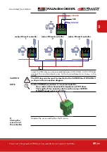
Connector for: 24 V dc service power supply, nozzle contact, pulser,
level 1 and 2 contact
•
Controller PG connection
•
Closing the rear cover of the controller
•
ocio connection on RS485 (if used)
•
interface connection with other canbus control units
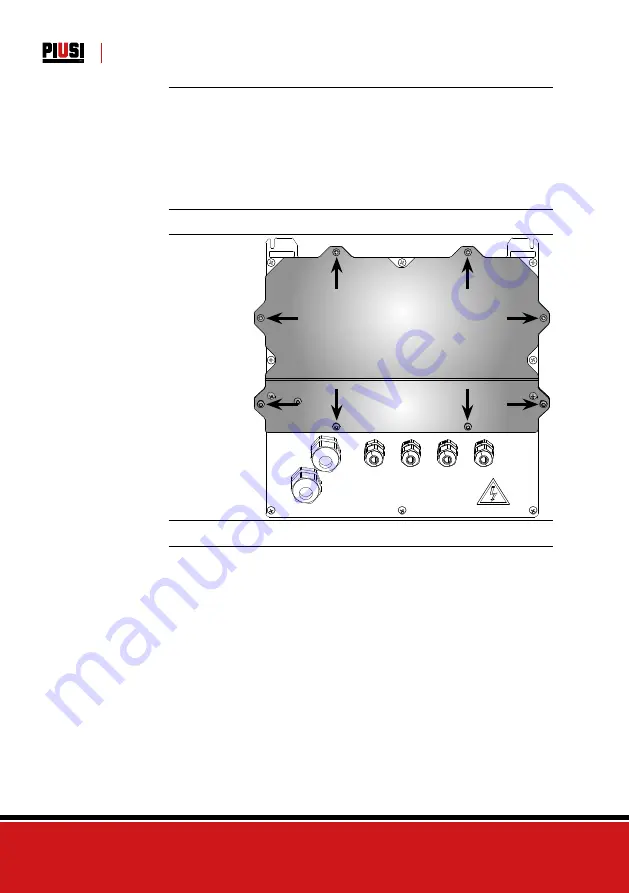
OPENING THE
REAR COVER
OF THE
CONTROLLER
Loosen all 8 screws of the rear cover of the controller to access the
compartment of the electronic boards
CABLE GLAND
CONNECTION
The cable glands to be used for the various signals are indicated in order
to obtain an optimised cable route inside the controller


