background image

www.pivotcycles.com

info@pivotcycles.com

1.877.857.4868

23

Notes:

Summary of Contents for SHUTTLE SL

Page 1: ...Original Operational Instructions SHUTTLE SL...

Page 2: ...hrough the steps necessary to set up all the components and become familiar with the FAZUA E bike System This document contains some helpful diagrams and reference material to make sure you have every...

Page 3: ...ng on the Fox 36 34 Forks 5 3 Charging 6 Charging the Battery 6 4 FAZUA System Basics 6 Control Elements Ring Control LED Hub 6 Powering the System ON and OFF 7 Support Modes 7 Boost Mode 8 Walk Assis...

Page 4: ...ange 55 125 rpm Protection type IP54 Weight approx 4 3 lbs 1 95 kg Operating temperature 23 F to 113 F 5 C to 45 C ambient temperature TECHNICAL DATA ON THE BATTERY Model Designation FAZUA ENERGY 430...

Page 5: ...plugging the power cable into the power inverter 2 Connect the charger to an outlet 3 Open the magnetic cover over the bikes charging port 4 Plug the power cable into the bikes charging port To ensur...

Page 6: ...oving or adding air so that steps 4 7 result in the O ring lining up with the red line on the sag indicator fig 4 When adjusting air pressure in the shock cycle the shock before re checking sag so the...

Page 7: ...ween fully open and firm for climbing The firm setting is best suited for long fire road climbs and smooth XC courses Because all dw link equipped Pivot bikes pedal so efficiently we use the compressi...

Page 8: ...l The below chart is adjusted to reflect our recom mended pressures RIDER WEIGHT FOX 36 AIR PRESSURE FOX 34 AIR PRESSURE kg lbs 55 59 120 130 58 psi 4 0 bar 50 psi 3 4 bar 59 64 130 140 62 psi 4 3 bar...

Page 9: ...icks The recommended starting points may need to be adjusted based on rider weight Lighter riders may prefer less compression damping fewer clicks from open Setting Compression Damping on the Fox 36 G...

Page 10: ...pletely charged before the first use 1 Prepare the charger by plugging the power cable into the power inverter 2 Connect the charger to an outlet 3 Open the magnetic cover over the bikes charging port...

Page 11: ...n the left side of the handlebars 2 Power the system on by pressing the controller up for at least 2 seconds The five LEDs on the LED Hub will illuminate 3 Once the power up sequence is complete the l...

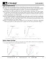
Page 12: ...tts for a short time to give you an extra push The duration of Boost mode depends on when you activate it Press and hold the switch up for at least one second to activate the boost function The lights...

Page 13: ...rider power and motor support This parameter is defined by setting at what rider power input the maximum motor power output is reached This value can vary between 90 420 W This relationship is illustr...

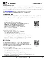
Page 14: ...oth in the phone settings 3 Turn on the Ride 60 drive system fitted to your e bike 4 In the FAZUA Rider app either select Tap to Pair Vehicle in the start screen or go to the menu in the upper left co...

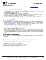
Page 15: ...ps FAZUA com Download Desktop Software FAZUA Toolbox 1 Go to the website listed above and click on the Desktop Software link 2 On the next page select the operating system of your device click on the...

Page 16: ...etting the maximum motor power output is higher which increases battery consumption and reduces range The Moderate setting is a balance between power output and energy consumption Support Relation Low...

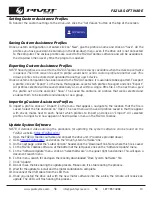
Page 17: ...rofiles you have saved can be called up in the drop down menu even if the drive unit is not connected to the computer The various profiles are saved to the FAZUA Toolbox software and will be available...

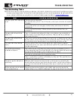
Page 18: ...rectly located If they intact and still showing the fault take your bike to an authorized Pivot dealer for service The white LEDs of the LED Hub Flash Software update After a new firmware update the c...

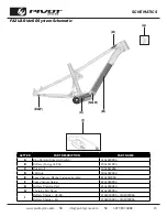
Page 19: ...fix 20A101100A C Drive Unit 10A101100A D LED Hub 30A102200A E Speed Sensor Magnet included on rotor 61A101100A F Speed Sensor Holder 61A103000A G Battery Charging Port 61A102000A H Charging Port Cover...

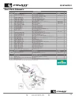
Page 20: ...SSLV1 BATT V1 R1 Battery Bracket Mounting Plate 27 FP SCW BTN M6 12 V1 R1 M6x12 Button Head Battery Bracket Mounting Screw 28 FP PLT CBL ROUTING V1 R1 Cable Routing Plate 29 FP CVR MTR EBIKE V1 R1 Sp...

Page 21: ...www pivotcycles com info pivotcycles com 1 877 857 4868 17 Wiring Diagram SCHEMATICS Ring Control Wire LED Hub Wire Speed Sensor Wire Charging Port Wire Shift Housing Brake Line Dropper Post Housing...

Page 22: ...the Shuttle SL to display cadence or power 1 On the Garmin select the three horizontal bars at the lower right of the screen to access the main menu 2 Select Sensors 3 Select either Cadence or Power T...

Page 23: ...w all charging instruction and do not charge the battery outside of the temperature range specified in the instructions Charging improperly or at temperatures outside of the specified range may damage...

Page 24: ...arger check all individual parts mains adapter mains cable charging cable and all plugs for damage If the charger s power cord is damaged it must be replaced by the manufacturer their customer service...

Page 25: ...gainst harmful interference in a residential installation This equipment generates uses and can radiate radio frequency energy and if not installed and used in accordance with the instructions may cau...

Page 26: ...www pivotcycles com 22 Notes...

Page 27: ...www pivotcycles com info pivotcycles com 1 877 857 4868 23 Notes...

Page 28: ...6720 South Clementine Court Tempe AZ 85283 T 1 480 467 2920 info pivotcycles com www pivotcycles com...

Reviews: