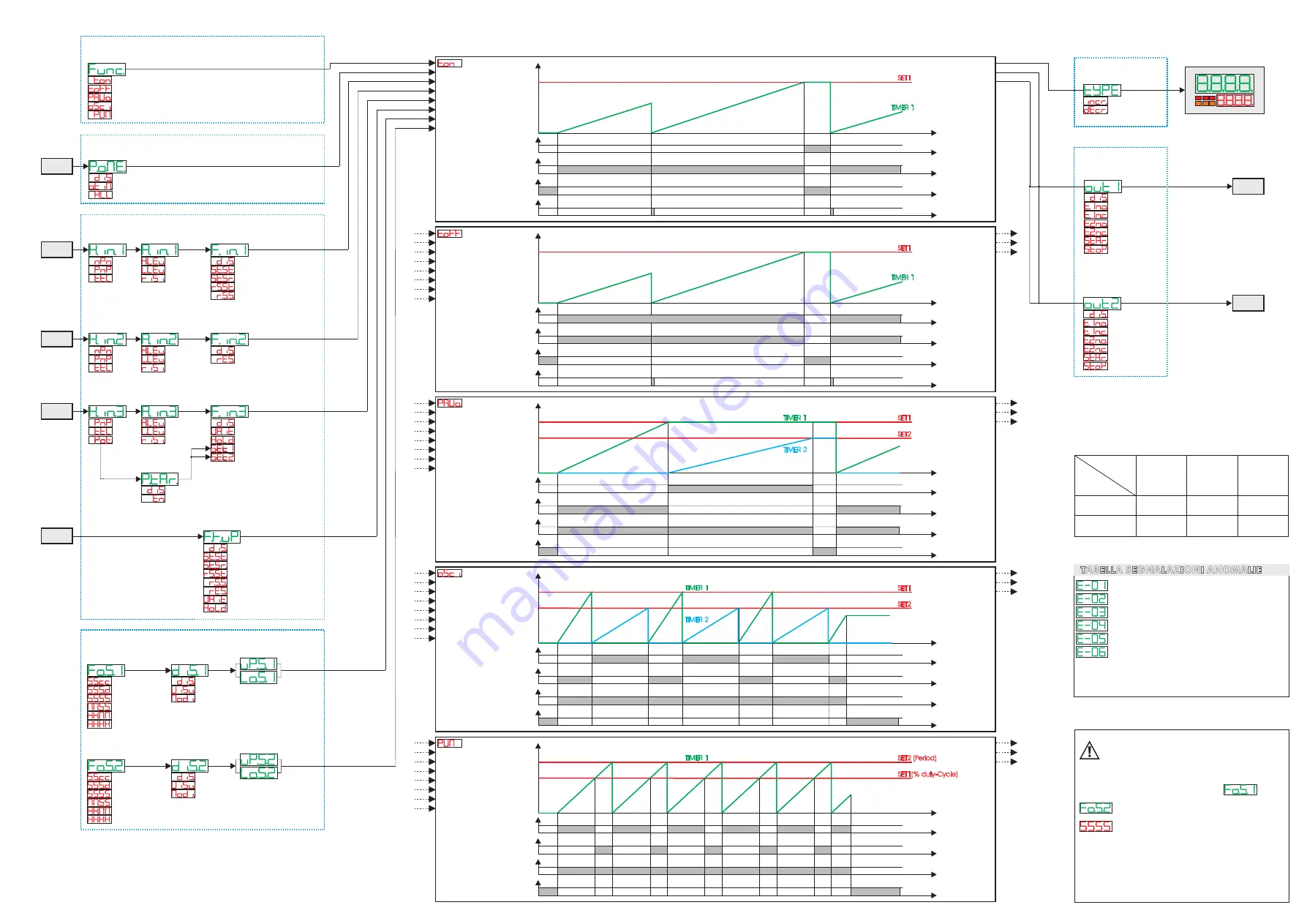
Timer On
Stop/Reset
Start/Stop/Reset
Reset
Wait/Hold/Set1-2
Timer Off
Start/Stop/Reset
Reset
Wait/Hold/Set1-2
Start/Stop/Reset/Wait/Hold
Oscillator
Start/Stop/Reset
Reset
Wait/Hold/Set1-2
Start/Stop/Reset/Wait/Hold
PWM
Start/Stop/Reset
Reset
Wait/Hold/Set1-2
Start/Stop/Reset/Wait/Hold
Pause / Work
Start/Stop/Reset
Reset
Wait/Hold/Set1-2
Start/Stop/Reset/Wait/Hold
TCT201-1ABC “TIMER”
P-01
Timer
Function
Timer On
Timer Off
Pause/Work
Oscillator
PWM
(Nota 1)
(Nota 1)
(Nota 1)
FUNCTION CONFIGURATION
P-02
Power-off
Memory
Disable
Only Timer
Timer / State
POWER-ON
RESET
BACKUP MEMORY CONFIGURATION
Timer value
Out Timer 1
Out Timer 2
Start/Stop/Reset/Wait/Hold
Set1
Set2
Stop/Reset
Set1
Set2
Stop/Reset
Set1
Set2
Stop/Reset
Set1
Set2
Stop/Reset
Set1
Set2
P-06
Active State
Input 1
High Level
Low Level
Rising edge
Disable
Start / Stop
Start / Stop-Reset
Reset-Start / Stop
Reset / Start / Stop
(Nota 2)
(Nota 3)
(Nota 4)
(Nota 5)
P-09
Function
Input 1
I1
P-03
Hardware
Input 1
NPN
PNP
TTL
Disable
Start / Stop
Start / Stop-Reset
Reset-Start / Stop
Reset / Start / Stop
(Nota 2)
(Nota 3)
(Nota 4)
Reset
Wait
Hold
P-12
Function
Key UP
Key UP
P-07
Active State
Input 2
High Level
Low Level
Rising edge
I2
P-04
Hardware
Input 2
NPN
PNP
TTL
Disable
Reset
P-10
Function
Input 2
P-08
Active State
Input 3
High Level
Low Level
Rising edge
I3
P-05
Hardware
Input 3
PNP
TTL
Potent.
Disable
Wait
Hold
Potent. To SET1
Potent. To SET2
P-11
Function
Input 3
P-24
Potentiometer
tarature
Disable
Enable
INPUT CONFIGURATION
Second.Cent
Second.Decimal
Second
Minute.Second
Hour.Minute
Hour
P-16
Format
Set 1
Disable
Visualized
Modifiable
P-18
Display
Set 1
P-20
Lower limit
Set 1
P-21
Upper limit
Set 1
Disable
Visualized
Modifiable
Second.Cent
Second.Decimal
Second
Minute.Second
Hour.Minute
Hour
P-17
Format
Set 2
P-19
Display
Set 2
P-22
Lower limit
Set 2
P-23
Upper limit
Set 2
SETPOINT CONFIGURATION
Timer value
Out Timer 1
Out Timer 2
Timer value
Out Timer 1
Out Timer 2
Timer value
Out Timer 1
Out Timer 2
Timer value
Out Timer 1
Out Timer 2
Q2
Q1
P-13
Output Q1
Setup
Disable
Out Timer 1 n.o.
Out Timer 1 n.c.
Out Timer 2 n.o.
Out Timer 2 n.c.
Start
Stop
P-14
Output Q2
Setup
Disable
Out Timer 1 n.o.
Out Timer 1 n.c.
Out Timer 2 n.o.
Out Timer 2 n.c.
Start
Stop
OUTPUT CONFIGURATION
DISPLAY CONFIGURATION
P-15
Type
of Timer
Incremental
Decremental
1
2
3
Set
Set
SET1
Time
1
0
Out Timer 1
Start
Stop
Reset
TIMER 1
1
0
1
0
1
0
Set
Set
SET1
Time
1
0
Out Timer 1
Start
Stop
Reset
TIMER 1
1
0
1
0
1
0
Set
Set
SET1
Time
1
0
Out Timer 1
Out Timer 2
Start
Stop
TIMER 1
1
0
1
0
1
0
SET2
TIMER 2
Set
Set
SET1
Time
1
0
Out Timer 1
Out Timer 2
Start
Stop
TIMER 1
1
0
1
0
1
0
SET2
TIMER 2
Set
Set
SET2 (Period)
Time
1
0
Out Timer 1
Out Timer 2
Start
Stop
TIMER 1
1
0
1
0
1
0
SET1(% duty-Cycle)
In modalità funzionamento PWM la
selezione del parametri 16
e 17
formato SET1 e SET2 è limitata a
(secondi).
Anche il limite minimo e massimo del
SET1 (legato alla percentuale di lavoro
o Duty Cycle) viene limitato in un range
da 0 a 100 (%).
ERRORE SCRITTURA MEMORIA EEPROM
(Nota 6)
TABELLA SEGNALAZIONI ANOMALIE
Nota 6:
Nota 7:
Spegnere e riaccendere lo strumento; se l’errore persiste
contattare il servizio assistenza.
Batteria ricaricabile scarica, lasciare acceso lo strumento
per consentirne la ricarica.
ERRORE LETTURA MEMORIA EEPROM
(Nota 6)
PARAMETRI ERRATI
(Nota 6)
DATI DI TARATURA ERRATI
(Nota 6)
DATI DI STATO ERRATI
(Nota 6)
REGISTRI DI BACKUP ERRATI
(Nota 7)
Nota 1:
Nota 2:
In questo funzionamento del timer, se
Questa funzione non azzera mai il valore del timer, quindi necessita di un ingresso per il reset.
P-06 Active State Input 1 = Rising Edge o P-09 Function Input 1 = Disable,
al termine del conteggio (raggiungimento del set), il timer si porta automaticamente in STOP.
Questa funzione esegue l’azzeramento del timer nell’istante del comando di STOP.
Questa funzione esegue l’azzeramento del timer nell’istante del comando di START.
Questa funzione è attiva solo se P-06 Active State Input 1 = Rising Edge
Nota 3:
Nota 4:
Nota 5:
Livello
logico
H
L
Ingresso
NPN
< 4,7 v
> 5,7 v
Ingresso
PNP
>5,7 v (I1, I2)
>12,4 v (I3)
< 4,7 v (I1, I2)
< 10,2 v (I3)
Tipo di
ingresso
Ingresso
TTL
>2,5 v
< 2,0 v


