7/24
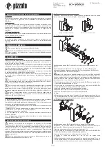
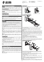
- For an operator standing outside the machine, it must be impossible to activate the
release button when the door is closed.
- The personnel concerned must be adequately trained on correct button operation,
so as to avoid any improper use (i.e. the button must not be used as a clothes-hook).
-
If the release button included in articles VN RR-K1 and
VN RR-K4 is not used, the installer must provide for a remote release operation which:
1) Should comply with EN ISO 14119.
2) Should guarantee the correct cable tension.
3) Must travel far enough to unlock the switch in a stable manner.
- Do not stress the device with bending and torsion.
- Do not modify the device for any reason.
- Do not exceed the tightening torques specified in the present operating instructions.
- The device carries out an operator protection function. Any inadequate installation
or tampering can cause serious injuries and even death, property damage, and eco-
nomic losses.
- If the machine where the device is installed is used for a purpose other than that
specified, the device may not provide the operator with efficient protection.
- Before installation, make sure the device is not damaged in any part.
- Do not paint or varnish the device.
- Do not drill the device.
- Do not use the device as a support or rest for other structures, such as raceways,
sliding guides or similar.
- Before commissioning, make sure that the entire machine (or system) complies with
all applicable standards.
- The fitting surface of the device must always be smooth and clean.
- The documents necessary for a correct installation and maintenance are always
available in the following languages: English, French, German and Italian.
- Should the installer be unable to fully understand the documents, the product must
not be installed and the necessary assistance may be requested (see paragraph
SUPPORT).
Always attach the following operating instructions to the manual of the machine in
which the device is installed.
- These operating instructions must be kept available for consultation at any time and
for the whole period of use of the device.
6.2 Do not use in the following environments
Attention: Do not use in environments where dust and dirt may in any way
penetrate the device interior and deposit there.
- In environments where continual changes in temperature cause the formation of
condensation inside the device.
- In environments where the application causes collisions, impacts or strong vibrations
to the device.
- In environments containing explosive or inflammable gases or dusts.
- In environments where ice can form on the device.
- In environments containing strongly aggressive chemicals, where the products used
coming into contact with the device may impair its physical or functional integrity.
- Prior to installation, the installer must ensure that the device is suitable for use under
the ambient conditions on site.
6.3 Maintenance and functional tests
Attention: Do not disassemble or try to repair the device. in case of any
malfunction or failure, replace the entire device.
Attention: In case of damages or wear it is necessary to change the whole
device. Correct operation cannot be guaranteed when the device is deformed or
damaged.
- The installer is responsible for establishing the sequence of functional tests to which
the device is to be subjected before the machine is started up and during maintenance
intervals.
- The sequence of the functional tests can vary depending on the machine complexity
and circuit diagram, therefore the functional test sequence detailed below is to be
considered as minimal and not exhaustive.
- Perform the following sequence of checks before the machine is commissioned and
at least once a year (or after a prolonged shutdown).
1) Check that the push button is firmly fixed to the machine.
2) Check that all the parts that make up the device are fixed together securely.
3) Check that the connection block is firmly fixed to the safety switch.
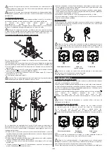
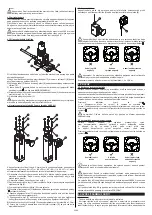
4) Check that the actuation cable is properly tensioned and that the square indicator
which is located in the connection block on the switch is positioned at the symbol.
If necessary, adjust the cable tension by adjusting the appropriate settings (see
Cable Tensioning paragraph).
5) Check that the protective sheath of the Bowden cable is not damaged or excessi-
vely bent and that the cable can slide freely inside it without friction.
6) Perform some actuation tests and check that the button moves freely.
7) Perform some actuation tests and check that the activation of the button causes
the release of the switch and the immediate stoppage of the machine and allows the
protection to be easily opened: the square indicator, which is located in the connec-
tion block on the switch, must be positioned at the symbol.
8) After unlocking, reset the device and check that the square indicator, which is loca-
ted in the connection block on the switch, is positioned at the symbol.
9) All external parts must be undamaged.
10) If the device is damaged, replace it completely.
- The device has been created for applications in dangerous environments, therefore it
has a limited service life. Although still functioning, after 20 years from the date of ma-
nufacture the device must be replaced completely. The date of manufacture is placed
next to the product code (see paragraph MARKINGS).
6.4 Additional prescriptions for safety applications with operator protection
functions
Provided that all previous requirements for the devices are fulfilled, for installations
with operator protection function additional requirements must be observed.
- The utilization implies knowledge of and compliance with following standards:
EN iSo 13849-1, EN 62061, EN iSo 14119, EN iSo 12100.
6.5 Limits of use
- Use the device following the instructions, complying with its operation limits and the
standards in force.
- The devices have specific application limits (min. and max. ambient temperature, me-
chanical endurance, IP protection degree, etc.) These limitations are met by the device
only if considered individually and not as combined with each other.
- The manufacturer’s liability is to be excluded in the following cases:
1) Use not conforming to the intended purpose;
2) Failure to adhere to these instructions or regulations in force;
3) Fitting operations not carried out by qualified and authorized personnel;
4) Omission of functional tests.
- For the cases listed below, before proceeding with the installation contact our technical
assistance service (see paragraph SUPPORT):
a) in nuclear power stations, trains, airplanes, cars, incinerators, medical devices or any
application where the safety of two or more persons depend on the correct operation
of the device;
b) cases not listed in these operating instructions.
7 MARKINGS
The outside of the device is provided with external marking positioned in a visible place.
Marking includes:
- Producer trademark
- Product code
- Batch number and date of manufacture. Example: A21 NS1-123456. The batch's first
letter refers to the month of manufacture (A=January, B=February, etc.). The second and
third letters refer to the year of manufacture (21 = 2021, 22 = 2022, etc.).
8 TECHNICAL DATA
8.1 Housing
Housing made of glass fibre reinforced technopolymer, self-extinguishing and shock-
proof.
Protection degree:
IP44 acc. to EN 60529 for the remote
release device
IP67 acc. to EN 60529 at safety switch
8.2 Cable
Internal cable in galvanised steel with external PVC sheath and internal steel spiral.
Maximum number of bends:
4
Minimum bending radius:
100 mm
8.3 General data
Ambient temperature:
-20°C … +50°C
Storage temperature:
-40°C … +75°C
Mission time:
20 years
Mechanical endurance:
100,000 operating cycles
Max. actuation frequency:
600 operating cycles/hour
8.4 Compliance with standards
EN ISO 14119
8.5 Compliance with the requirements of:
Machinery Directive 2006/42/EC, RoHS Directive 2011/65/Eu
9 SPECIAL VERSIONS ON REQUEST
Special versions of the device are available on request.
The special versions may differ substantially from the indications in these operating
instructions.
The installer must ensure that he has received written information from the support
service regarding installation and use of the special version requested.
10 DISPOSAL
At the end of service life product must be disposed of properly, according to the rules in
force in the country in which the disposal takes place.
11 SUPPORT
The device can be used for safeguarding people’s physical safety, therefore in case of
any doubt concerning installation or operation methods, always contact our technical
support service:
Pizzato Elettrica Srl
Via Torino, 1 - 36063 Marostica (VI) - ITALY
Tel39.0424.470.930
E-mail tech@pizzato.com
www.pizzato.com
Our support service provides assistance in Italian and English.
12 EC CONFORMITY DECLARATION
I, the undersigned, as a representative of the following manufacturer:
Pizzato Elettrica Srl - Via Torino, 1 - 36063 Marostica (VI) – ITALY
hereby declare that the product is in conformity with whatever prescribed by the 2006/42/
EC Machine Directive. The complete version of the present conformity declaration is
available on our website www.pizzato.com
Marco Pizzato
DiSCLAiMER:
Subject to modifications without prior notice and errors excepted. The data given in this sheet are accu-
rately checked and refer to typical mass production values. The device descriptions and its applications,
the fields of application, the external control details, as well as information on installation and opera-
tion, are provided to the best of our knowledge. This does not in any way mean that the characteristics
described may entail legal liabilities extending beyond the “General Terms of Sale”, as stated in the
Pizzato Elettrica general catalogue. Customers/users are not absolved from the obligation to read and


