background image

Note:  This calibration procedure does not require, nor should it involve a scope, frequency counter, electronic tuner or any other test
equipment used for measuring period or frequency outside of what was provided to you by nature...your ears.  Our reasons for this are
simple:  You do not use these devices while making music, nor does your audience while listening to you make music.  Your ears are all
that’s needed, and therefore all that required for this calibration.  These test devices will give you readings which may make you think
your VCO are not functioning properly.  While a perfectionist may argue that this constitutes a faulty, sub-standard musical instrument,
 we feel that all these devices will do is verify the obvious - that you’re adjusting the tracking of a musical instrument, not a piece of lab
gear.  Your results will not be perfect.  If you wish to use test equipment to verify this, feel free.  However, your results will tune the
tracking of your M15’s so that they are musical, phat and payable.  There’s a big big difference between these two extremes.

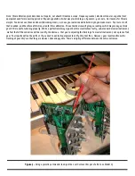
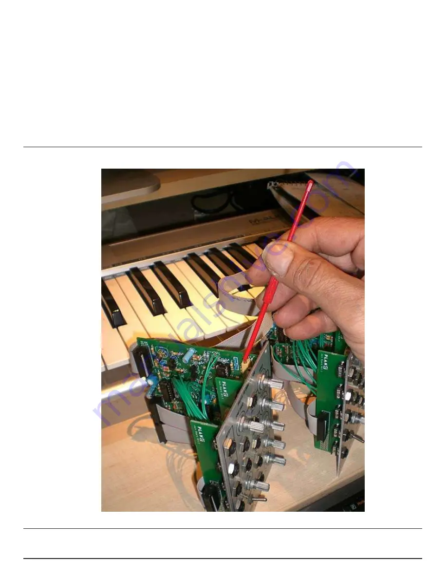
Figure 3 -

 Using a placstic pot tweeker to adjust the 1 volt/octave trim pot of a Rev 1.xx Model 15

Summary of Contents for 15 Complex VCO

Page 1: ...each of you because all of each and every user s operating conditions vary Step One The Right Tools for the Job Most important rule in doing any job make sure you ve got the correct tools to do it correctly The following may require a small investment on your part but the rewards will pay off immediately The tools you ll need for this cal are in two groups 1 1V OCT ADJUSTMENT A Adapter power cable...

Page 2: ...Once your connector is positioned where you want it and it s sitting straight perpendicular to the cable not cocked or crooked apply soft hand pressure and close the connector so that the teeth begin to bite into the ribbon cable Do this enough so that it stays in position You can t apply enough pressure manually to complete the crimp don t try for this you need a table vise or a tool especially m...

Page 3: ...not have to concern itself with high frequency compensation as do saw core VCOs which require that a mutli step process be repeated again and again to dial in accuracy The 1v octave cal of a Plan B VCO is much easier 1 Connect the power cables to the modules MAKING SURE PIN 1 RED BAND is correctly oriented see figure 1 VERY IMPORTANT NOTE FIGURE 1 SHOWS TWO REV 1 MODEL 15 S ON REV 2 MODEL 15 S ELE...

Page 4: ...ns of trim pots in Rev 2 XX Model 15 s LEGEND A 1 VOLT PER OCTAVE ADJUSTMENT POT B TRIANGLE SYMMETRY ADJUSTMENT POT C SINE PURITY ADJUST D RAMP SYMMETRY POT LEGEND A 1 VOLT PER OCTAVE ADJUSTMENT POT B TRIANGLE SYMMETRY ADJUSTMENT POT C SINE PURITY ADJUST D RAMP SYMMETRY POT ...

Page 5: ...ch BYPASSES ANY FILTERING EFFECTS or PROCESSING A RAW WAVEFORM IS REQUIRED A3 With your Model 15 sounding continuously in the speakers play and hold a C1 on your midi keyboard While sustaining that note tune your Model 15 so that it is in tune with the pitch coming from your reference digital instrument This is probably the most critical part of this test Take your time tune carefully for the mini...

Page 6: ...ices will give you readings which may make you think your VCO are not functioning properly While a perfectionist may argue that this constitutes a faulty sub standard musical instrument we feel that all these devices will do is verify the obvious that you re adjusting the tracking of a musical instrument not a piece of lab gear Your results will not be perfect If you wish to use test equipment to ...

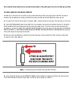
Page 7: ... you re powering your Model 15 form TO do this simply run another patchcord from your Model 15 and attach an alligator test cable FROM THE RING GROUND portion of the open end of the patch cable TO THE GROUND INPUT OF THE SCOPE or ATTACH THE ALLIGAZTOR GROUND CLIP PROVIDED ON YOUR SCOPE PROBE to eh GROUND RING of the open end of the patch cord you re using for ground connection B3 Before you make a...

Page 8: ...h half of the ramp wave meet butt against one another i e come in contact with one another at ground Pay close attention to Figure 7 as a reference It is possible to adjust your ramp 90 degrees out of phase by making the wrong ends of each half butt against one another moving the trim pot the full extent of it s travel will quickly give you an indicaiton of which is the correct alignment Use FIgur...

Page 9: ...5 MS DIV ADJUST TRIMPOT RV2 TRI ADJ SO THAT TRIANGLE WAVE IS SYMMETRICAL TO GROUND 0 VOLTS O VOLTS HORIZONTAL SCALE 2V DIV VERTICAL SCALE 5 MS DIV TOO FAR ON THE HIGH END NOT SYMMTRICAL AROUND GROUND FIG 5 CALIBRATION No 2 TRIANGLE SYMMETRY GOOD BAD ...

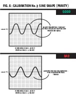
Page 10: ... MS DIV ADJUST TRIMPOT RV5 SINE ADJ SO THAT THE ARC OF THE PEAK AND TROUGH ARE EQUAL FIG 6 CALIBRATION No 3 SINE SHAPE PURITY GOOD BAD O VOLTS HORIZONTAL SCALE 2V DIV VERTICAL SCALE 5 MS DIV ADJUSTED TOO FAR ON LOWER END PEAK IS NARROWER THAN TROUGH ...

Page 11: ...ENDS MEET FIG 7 CALIBRATION No 4 RAMP WAVE SYMMETRY GOOD BAD O VOLTS HORIZONTAL SCALE 2V DIV VERTICAL SCALE 5 MS DIV NEGATIVE SIDE SLIGHTY OFFSET DOES NOT MEET WITH POSITIVE END O VOLTS NEGATIVE SIDE GROSSLY OFFSET WAVE APPEARS OK BUT NEGATIVE END IS ACTUALLY 90 OUT OF PHASE TOO HIGH AND IS DOUBLING BASE FREQUENCY ...

Reviews: