EL240.128.45 Operations Manual (020-0345-00C)
7
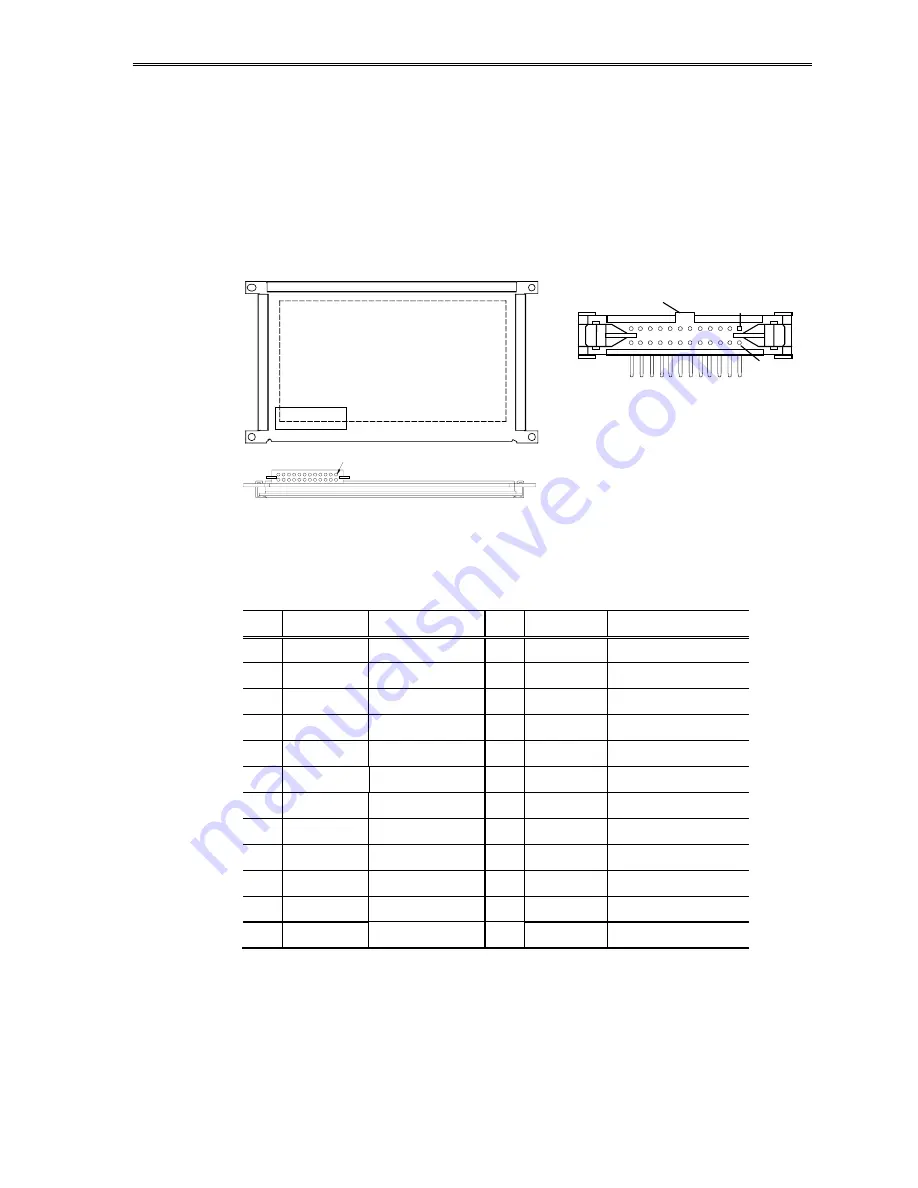
Connector
Video signals and DC power are supplied to the display through a single
24-pin, dual-row, 2 mm pitch square pin, right-angle, locking connector:
Samtec part number EHT-112-01-S-D-RA, or an equivalent connector
matching the pinouts in Table 3. The mating connector is the Samtec
TCSD family of cable strips. Consult your Samtec representative (1-800-
SAMTEC9) for cable and connector options.
J1
Pin 1
(Back of display)
(Bottom of display)
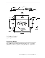
Figure 2. Data/Power Connector – J1.
Table 3. Connector Pinouts J1.
Pin Signal
Description
Pin Signal
Description
1
V
H
Display voltage
2
V
H
(+12
V)
3 GND
Ground 4 GND
Ground
5
V
L
(+5 V)
Logic voltage
6
RES
Reset
7 /WR
Write 8 /RD
Read
9 /CS Chip
Select
10 A0
Address
11 SELFTES
12 GND
Ground
13 D0 input/output
14 D1
input/output
15 D2 input/output
16 D3
input/output
17 D4 input/output
18 D5
input/output
19 D6 input/output
20 D7
input/output
21 SEL1
Select 22
READY Display
ready
23 GND
Ground 24 LUMA Luminance
control
(Viewed from top of connector)
Key
Pin 2
Pin 1


