background image


EL320.256-FD7 Operations Manual (020-0353-00A) 

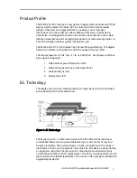
The EL320.256–FD7 display includes a light absorbing ICE ( Integrated Contrast 
Enhancement) construction of the display glass. ICE construction significantly 
improves the luminance contrast of the display in bright ambient. The ICE also 
removes the halo around the lit pixels in dark ambient making the appearance 
of each pixel extremely crisp and clear.  

In the EL320.256-F Series, the 320 column electrodes and 256 row electrodes 
are  arranged in an  X-Y  formation with the intersecting areas performing as 
pixels. Voltage  is   applied  to  both  the  correct  row electrode  and the 
correct column electrode to cause a lit pixel. Operating  voltages required are 
provided by an integral DC/DC converter. 

Electrical Characteristics 

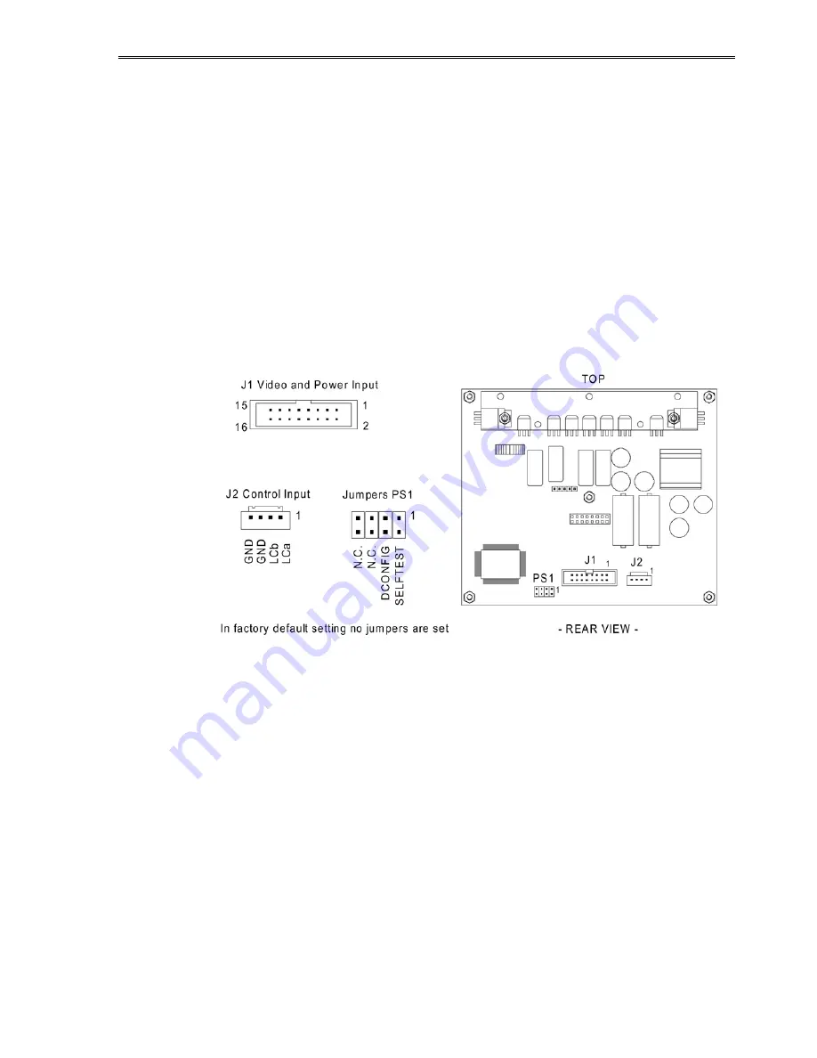
Connector Layout 


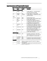
Fig 2. Input Connectors and Programmable Jumpers. 


Summary of Contents for EL320.256-FD7

Page 1: ...EL320 256 FD7 320 x 256 Pixel High Brightness High Contrast Display USER S MANUAL www planar com...

Page 2: ...Revision Control Date Description November 1997 Document number PI02355 Ver 3 June 2004 Document number 020 0353 00A...

Page 3: ...ontrol 6 Two Bits Parallel 6 Self Test 6 Input Specifications 7 Timing Characteristics 7 Setup and Hold Timing 8 Operational Specifications 9 Environmental 9 Reliability 9 Safety 9 Electromagnetic Com...

Page 4: ...gure 6 Mechanical Dimensions 13 Tables Table 1 Input Connectors and Programmable Jumpers 5 Table 2 Connectors 6 Table 3 Input Specifications 7 Table 4 Timing Characteristics 8 Table 5 Setup and Hold T...

Page 5: ...requires 5 Vdc and 11 to 30 Vdc Vcc1 Vcc2 power and four basic signals to operate 1 Video Data or pixel information VID 2 Video Clock pixel clock or dot clock VCLK 3 Horizontal Sync HS 4 Vertical Syn...

Page 6: ...ixels in dark ambient making the appearance of each pixel extremely crisp and clear In the EL320 256 F Series the 320 column electrodes and 256 row electrodes are arranged in an X Y formation with the...

Page 7: ...ng edge of the VS 11 Horizontal Sync HS The horizontal sync signal HS controls the horizontal position of the picture The last 320 pixels before the fall of HS are displayed 13 Video Clock VCLK The VC...

Page 8: ...the DC DC converter All high voltages required for display glass access are generated internally Display Features Luminance Control The luminance of the display can be adjusted from below 10 up to fu...

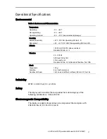
Page 9: ...rrent at 12V Icc2 60 Hz 0 25A 0 5A 120 Hz 0 5A 0 9A Power consumption 60 Hz 3 5W 6W 120 Hz 6W 11W Values verified at design not measured Operating conditions Ambient temperature 25 C Note Absolute max...

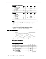
Page 10: ...20 320 tVCLK 4 T9 HS period tHS 19 s Notes 1 This time is needed to display the last row and to initiate the following frame 2 Only rising edge is used 3 2 tVCLK minimum 4 The number of VCLK pulses du...

Page 11: ...ft above sea level Standard IEC 68 2 13 Vibration 20 500 Hz ASD level 0 05 g2 Hz 30 min each axis Standard IEC 68 2 36 Random Vibration Test Fdb Shock Magnitude Duration Number of shocks 100 g 4 ms ha...

Page 12: ...nce Contrast Ratio MInimum 20 1 3 1 36 1 3 1 60HZ 500lx 60HZ 4500lx 120HZ 500lx 120HZ 9000lx Viewing Angle Minimum 160 Illuminance Classification 1 10 lx 10 100 lx 100 1000 lx 1000 10000 lx 10000 1000...

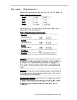
Page 13: ...y 256 vertical CAUTION The ambient temperature of the display should not be allowed to exceed the environmental specifications see page 9 In most applications an air gap of min5 mm is recommended see...

Page 14: ...event application of static charges on the display from the operator or tools The display is made of glass material and should be handled with proper care Do not drop the display or allow hard objects...

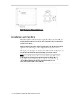
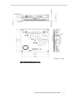
Page 15: ...EL320 256 FD7 Operations Manual 020 0353 00A 13 Fig 6 Mechanical dimensions in mm...

Page 16: ...placement of Goods is Seller s sole obligation and Buyer s exclusive remedy for all claims of defects If that remedy is adjudicated insufficient Seller shall refund Buyer s paid price for the Goods an...

Page 17: ...ased in Beaverton Oregon and Espoo Finland with a world wide sales distribution network Full application engineering support and service are available to make the integration of Planar displays as sim...

Page 18: ...5am 5pm Pacific Time Europe and Asia Pacific Support Olarinluoma 9 P O Box 46 FIN 02201 Espoo Finland Tel 358 9 420 01 Hours M F 7 00am 4pm CET 2004 Planar Systems Inc 06 04 Planar is a registered tra...

Reviews: