background image


7  

EL640.400-CB1/CB3 and –CD4 Operations Manual (020-0356-00A)


Display Features  

Display Operation Modes


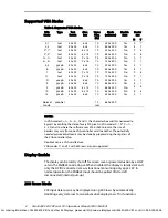
The displays have two input timing modes. VGA Mode supports standard 200, 
350 and 400 row VGA modes and Normal Mode is similar to Normal Mode in 
most Planar displays. The operation mode is determined from combination of 
the polarities of the VS and HS pulses and the _BLANK signal at the rising edge 
of the VS pulse and the polarities of VS and HS pulses at the rising edge of the 
_BLANK pulse. 

In VGA modes, the number of columns is determined by the number of VCLK 
pulses during a HS pulse. A tolerance of ±1 pulse is accepted. 

VGA Modes: The display data and control input is compatible with feature 
connector signals from VGA board. The display supports VGA modes 0, 1, 2, 3, 
0*, 1*, 2*, 3*, 0+, 1+, 2+, 3+, 4, 5, 6, 7, 7+, D, E, F, 10 and 13. It notifies the 
polarity of the HS and VS at the rising edge of BLANK and determines the 
number of rows in the mode. Note that in VGA modes 0, 1, 0*, 1*, 0+, 1+, 4, 
5, D and 13, where the software uses 320 or 360 columns, the size of 
borders varies from one VGA- controller to another. Therefore the image 
may not be centered properly using those modes.  

The image is centred automatically, and in text modes with 720 pixels 
horizontally, every ninth pixel is omitted for compatibility. The non-displayed 
pixel is in the space region of the character matrix, and therefore no 
information is lost. The borders are normally eliminated because of the 
centering. The upper and lower borders are however displayed in the modes 
using 350 rows due to extra rows not needed for the picture. 

The 480 row VGA modes are not supported. Even if the display does not scan 
in these modes (11, 12), it continues to operate with no failures when a 
supported mode is detected. 

Normal Mode: This mode is pin and timing compatible with MD640.400 Series 
displays and the Normal mode of EL640.400–C3/CD3 series displays. In this 
mode only four input signals are needed: video data (VID), video clock (VCLK), 
horizontal synchronizing (HS) and vertical synchronizing (VS). _BLANK is not in 
use and should be pulled high or left disconnected. 

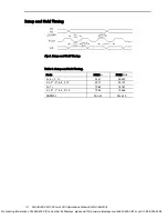
In Normal mode the last 640 pixels before the fall of the HS are displayed. The 
topmost row displayed is the first HS HIGH time ending after HS Hold from VS 
time (T4 in Normal Mode) from the rising edge of VS. If HS  is running 
continuously, the rising edge of the VS can be simultaneous to the previous 
falling or rising edge of the HS. See details on setup and hold timing as well as 
Normal Mode timing on page 14. 

For ordering information of EL640-400-CB1 and other EL Displays, please visit http://www.eldisplays.com/EL640-400-CB1 or call +1-888-394-4998.

Summary of Contents for EL640.400-CB1

Page 1: ...0 CB1 CB3 and CD4 640 x 400 Pixel Display USER S MANUAL www planar com For ordering information of EL640 400 CB1 and other EL Displays please visit http www eldisplays com EL640 400 CB1 or call 1 888...

Page 2: ...iption November 1997 Document number PI01064 Ver 3 June 2004 Document number 020 0356 00A For ordering information of EL640 400 CB1 and other EL Displays please visit http www eldisplays com EL640 400...

Page 3: ...orted VGA Modes 8 Display Enable 8 200 Rows Mode 8 Two Bit Parallel Data 9 Brightness Control 9 Self Test 9 Installation and Handling 9 Mounting 9 Handling 9 Cable Length 10 Avoiding Burn in 10 Timing...

Page 4: ...4 Back and Side Views 19 Figure 9 EL640 400 CB1 CB3 FRA and CD4 FRA Back and Side Views 20 Tables Table 1 Input to the Display 4 Table 2 Connectors 5 Table 3 PS1 6 Table 4 Input Specifications 6 Table...

Page 5: ...deo Data or pixel information 2 Video Clock pixel clock or dot clock 3 Horizontal Sync or Blanking 4 Vertical Sync EL Technology Planar EL displays consist of an electroluminescent glass panel and a m...

Page 6: ...d clear In Planar EL640 400 C displays the 640 column electrodes and 400 row electrodes are arranged in an X Y formation with the intersecting areas performing as pixels Voltage is applied to both the...

Page 7: ...of the picture 11 Horizontal Sync HS The horizontal sync signal HS controls the internal row counter and in the NORMAL mode the horizontal position of the picture 13 Video Clock VCLK The VCLK signal...

Page 8: ...ector compatible The display automatically determines the mode of operation The control input J2 includes contacts for optional luminance control and ENABLE signal to totally shut off the display when...

Page 9: ...ply voltage Logic supply current at 5 V Display Supply voltage CB1 CD4 CB3 Supply current at 12 V CB1 CD4 Supply current at 24 V CB3 Power consumption 5 V 12 V Power consumption 5 V 24 V Vcc1 Icc1 Vcc...

Page 10: ...horizontally every ninth pixel is omitted for compatibility The non displayed pixel is in the space region of the character matrix and therefore no information is lost The borders are normally elimina...

Page 11: ...In VGA modes 0 1 2 3 7 and 7 the character box width is narrowed to 8 pixels by omitting the data of every 9th pixel In VGA modes 0 1 0 0 1 4 5 D and 13 where the software uses 320 or 360 columns the...

Page 12: ...age to LUMPOT2 If the two inputs are left disconnected the brightness is at its maximum level Self Test The operation of the display can be easily checked without any external signals by the self test...

Page 13: ...ignal source Avoiding Burn in As with any other light emitting display luminance variations may be noticed if fixed patterns are displayed on the screen for extended periods It is prudent to use a scr...

Page 14: ...tHS T5 Vertical Border 6 tHS HS pulses VS 449 VS frequency 70 Hz Description 320 640 720 Unit T6 Horizontal Border 0 8 9 tVCLK T7 Horizontal Front Porch 8 8 9 tVCLK T8 HS Pulse Width 48 96 108 tVCLK...

Page 15: ...7 tHS HS pulses VS 449 VS frequency 70 Hz Description 320 360 640 720 Unit T6 Horizontal Border 0 0 8 9 tVCLK T7 Horizontal Front Porch 8 9 8 9 tVCLK T8 HS Pulse Width 48 54 96 108 tVCLK T9 Horizonta...

Page 16: ...ption Min Typ Unit T4 HS setup to VS 9 tVCLK T5 HS hold from VS 2 s T6 HS Low Time 5 4 tVCLK T7 HS High Time 6 640 640 tVCLK T8 HS period tHS 31 s 1 This is the time needed to display the last row and...

Page 17: ...Table 9 Setup and Hold Timing Mode tVCLK ns fVCLK MHz 2 3 7 7 35 31 28 322 2 3 2 3 6 E F 10 39 71 25 175 0 1 70 62 14 161 0 1 0 1 4 5 D 13 79 43 12 588 NORMAL Min 33 Max 30 For ordering information of...

Page 18: ...el Vibration 20 500 Hz ASD level 0 05 G2 Hz Random vibration wide band IEC 68 2 36 Test Fdb Shock Magnitude Duration Number of shocks 100 G 4 ms half sine wave 18 3 on each of the 6 surfaces IEC 68 2...

Page 19: ...ce Contrast Ratio Minimum CD4 7 1 500 lx 3 1 1800 lx Viewing Angle Minimum 160 Illuminance Classification 1 10 lx 10 100 lx 100 1 000 lx 1 000 10 000 lx 10 000 100 000 lx dark dim office bright sunlig...

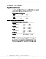
Page 20: ...height 121 8 4 80 width 195 0 7 68 Pixel Pitch millimeters inches height 0 305 0 012 width 0 305 0 012 Pixel Size millimeters inches height 0 178 0 007 width 0 212 0 008 Pixel fill factor 41 Pixel Mat...

Page 21: ...al 020 0356 00A 18 Active Area 195 0 x 121 8 0 212 0 305 0 178 0 305 Fig 7 Viewing Area Characteristics For ordering information of EL640 400 CB1 and other EL Displays please visit http www eldisplays...

Page 22: ...re connected Dimensions in mm inches 4 through holes M3 thread WARNING Check length of fastening screw Max 6 mm penetration Center of connector center of mounting holes to EMI layer and Systems GND TO...

Page 23: ...rame is connected to GND Dimensions in mm inches 1 PS1 1 1 J1 J2 Center of connector center of mounting holes 1 5 06 4 through holes M3 thread WARNING Check length of fastening screw Max 4 mm penetrat...

Page 24: ...djudicated insufficient Seller shall refund Buyer s paid price for the Goods and have no other liability to Buyer All warranty repairs must be performed at Seller s authorized service center using par...

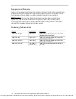
Page 25: ...rning goods for repair please include a brief description of the problem and mark the outside of the shipping container with the RMA number Ordering Information Product Part Number Description EL640 4...

Page 26: ...a 9 P O Box 46 FIN 02201 Espoo Finland Tel 358 9 420 01 Hours M F 7 00am 4pm CET 2004 Planar Systems Inc 06 04 Planar is a registered trademark of Planar Systems Inc ICE ICEBrite and ICEPlus are trade...

Reviews: