background image


EL640.480 AG1 Series User’s Manual (020-0350-00B) 


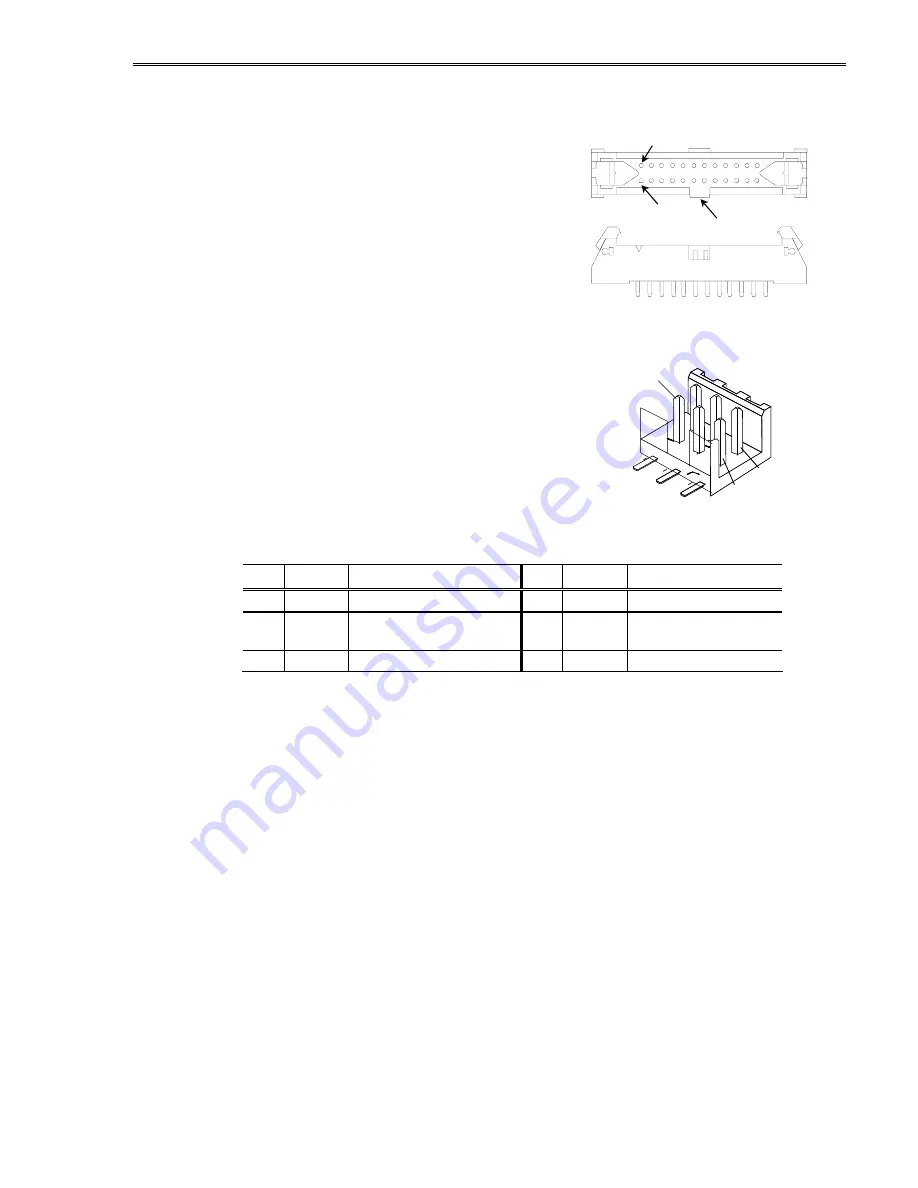
Locking Power and Data Connector 

The display may be ordered with an optional 20 
pin, 2 mm through-hole locking male header, 
Samtec EHT-110-01-S-D or equivalent. This 
locking connector is standard on the 
EL640.480-AG1 ET display. The mating 
connector is in the Samtec TCSD family of cable 
strips. Compatibility with  
non-Samtec equivalents should be verified 
before use.  

Dimming Connector J2 

The ET version of this display includes a J2 analog 
dimming circuit which is not available on the 
standard display. The J2 dimming connector is a 6-
pin, straight-locking header made by FCI, part 
number 98424-G52-06A. The recommended mating 
connector is an FCI 89947-306 (IDC) or FCI 77138-001 
and 90311-006 (crimp-to-wire receptacle plus 
housing) or equivalent.   


Table 4. J2 Connector Pinout. 

Pin Signal  Description 

Pin Signal  Description 

LUM   

Input for pot. 

GND 

Signal ground return 

SLF 

Self test mode selection, 
active low. 

4 NC 

No 

connect 

5 NC 

No 

connect 

6 NC 

No 

connect 


Key

Pin 1

Pin 2


Pin 6

Pin 5

Pin 1

Samtec EHT-110-01-S-D 

FCI 98424-G52-06A 

Summary of Contents for EL640.480-AG1 ET CC

Page 1: ...EL640 480 AG1 Series ICEBrite VGA Flat Panel Displays USER S MANUAL www planar com...

Page 2: ...Revision Control Date Description July 1999 Document number OM501 01 June 2004 Document number 020 0350 00 Rev A March 2005 Rev B ECO 2201 updated J1 connector information...

Page 3: ...asics 6 Power 6 Data and Power Connector 7 Locking Power and Data Connector 8 Dimming Connector J2 8 Interface Information 9 Video Input Signals 9 Self Test Mode 11 Optical Performance 12 Dimming 12 G...

Page 4: ...mensions 15 Tables Table 1 DC Input Voltage Requirements 6 Table 2 Video Input Requirements 6 Table 3 J1 Connector Pinouts 7 Table 4 J2 Connector Pinouts 8 Table 5 Video Input Timing 10 Table 6 Setup...

Page 5: ...is the low profile version of the AG1 ET Through simple design and advanced manufacturing technologies Planar s new VGA display family brings the visual performance and image quality of EL into cost...

Page 6: ...treatments and touch screens on the viewing side of the display To this end the glass extends in front of the mounting bezel by approximately 0 5 mm 0 02 It is imperative that any mounting scheme app...

Page 7: ...onics and the display glass are very sensitive to handling When cleaning the edges of the display glass special care should be taken not to damage the leads Cable Length A maximum cable length of 0 6...

Page 8: ...without exception to ensure the long term reliability of the display Planar does not recommend operation of the display outside these specifications Table 1 DC Input Voltage Requirements Parameter AG1...

Page 9: ...unit A low profile version display the EL640 480 AG1 LP uses the EHT110 01 S D RA right angle connector Consult your Samtec representative 1 800 SAMTEC9 for the cable connector options Table 3 J1 Conn...

Page 10: ...e ET version of this display includes a J2 analog dimming circuit which is not available on the standard display The J2 dimming connector is a 6 pin straight locking header made by FCI part number 984...

Page 11: ...ne of a frame is marked by S scan start up signal as shown in Figure 2 The end of each row of data is marked by CP1 as shown in Figure 2 and Figure 3 Input signals UD3 UD0 contain the video data for t...

Page 12: ...R tS21 tS12 tF tR tSU tHOLD tS3 tCLK tCL tCH Figure 2 Setup and Hold Timing Diagram Table 6 Setup and Hold Timing Symbol Name Min Max Unit tS21 CP1 allowance from CP2 0 ns tS12 CP2 allowance from CP1...

Page 13: ...s a self test mode composed of a 1x2 checkerboard pattern that inverts every few seconds The self test mode is entered by applying power to the display with the S signal static The display remains in...

Page 14: ...tness to be lowered proportionally by reducing the frame rate This is performed within the application by lowering the frame rate of the video input signals Because brightness is proportional to the f...

Page 15: ...s than their maximum frame rate For additional information refer to Planar Application Note 119 or contact Planar s Application Engineers Environmental Table 8 Environmental Characteristics Temperatur...

Page 16: ...s 18 0 0 7 Active Area millimeters inches Width Height Diagonal 165 1 6 5 123 8 4 8 205 0 8 1 Fill Factor 58 Pixel Pitch millimeters inches Width Height 258 0 010 258 0 010 Pixel Size millimeters inch...

Page 17: ...35 36 3 1 43 Optional Right Angle Connector 47 7 1 88 52 0 2 05 54 3 2 14 62 7 2 47 6 05 0 238 Typ 10 29 0 405 Typ 4 5 0 176 Typ 25 0 0 984 20 0 0 787 Component Envelope Clearance Envelope 0 25 0 010...

Page 18: ...repairs must be performed at Seller s authorized service center using parts approved by Seller Buyer shall pay costs of sending Goods to Seller on a warranty claim and Seller shall pay costs of return...

Page 19: ...support and service are available to make the integration of Planar displays as simple and quick as possible for our customers RMA Procedure For a Returned Material Authorization number please contact...

Page 20: ...F 5am 5pm Pacific Time Europe and Asia Pacific Support Olarinluoma 9 P O Box 46 FIN 02201 Espoo Finland Tel 358 9 420 01 Hours M F 7 00am 4pm CET 2004 Planar Systems Inc 06 04 Planar is a registered t...

Reviews: