EL640.480 AG1 Series User’s Manual (020-0350-00B)
7
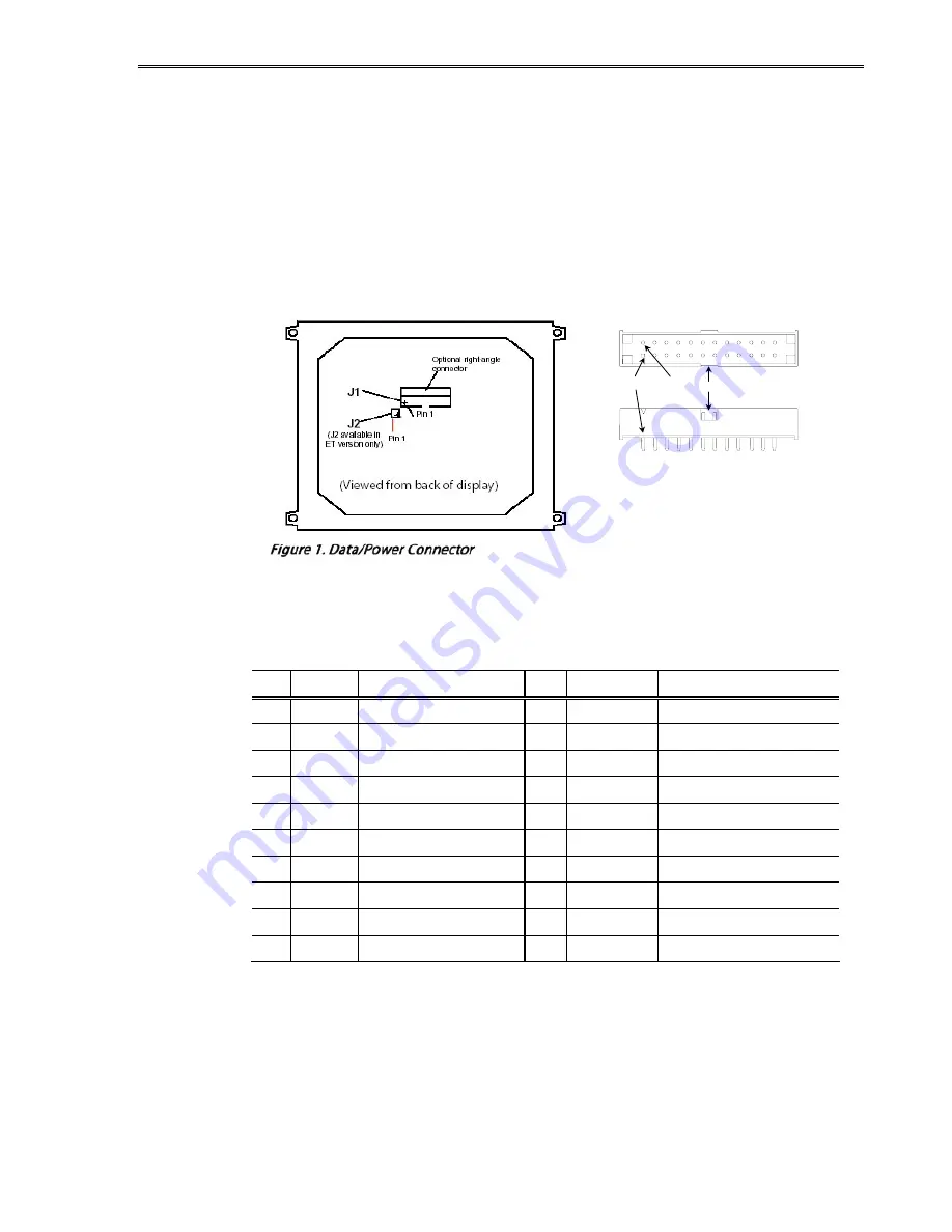
Data and Power Connector
The EL640.480-AG1 display uses the Samtec STMM-110-01-T-D and the
EL640.480-AG1 ET display uses the Samtec EHT-110-01-S-D or equivalent locking
connectors. Although these connectors differ slightly, their pinouts are identical
and are shown in the table below. The mating connector for both displays is in
the Samtec TCSD family of cable strips. The proper connector, user-specified
cable length, and connector configuration are supplied as a single unit. A low-
profile version display, the EL640.480-AG1 LP, uses the EHT110-01-S-D-RA right-
angle connector. Consult your Samtec representative (1-800-SAMTEC9) for the
cable/connector options.
Table 3. J1 Connector Pinouts.
Pin Signal Description
Pin Signal
Description
1
UD1 Video data (upper)
2
UD0
Video data (upper)
3
UD3
Video data (upper)
4
UD2
Video data (upper)
5
LD1
Video data (lower)
6
LD0
Video data (lower)
7
LD3
Video data (lower)
8
LD2
Video data (lower)
9
CP2
Data input clock
10
GND
Ground
11
CP1
Input data latch.
12
GND
Ground
13
S
Scan start-up signal
14
GND
Ground
15 GND Ground
16 GND Ground
17 V
L
+5 V Power
18
V
L
+5 V Power
19 V
H
+12 V Power
20
V
H
+12 V Power
Key
Pin 1
Pin 2
(Viewed from back of display)
Samtec STMM-110-01-T-D


