background image

EL552.256-Q2

4

EL552.256-Q2 Operations Manual (OM410-00)

Avoiding Burn-In

As with other light emitting displays, displaying fixed patterns on the screen can
cause burn-in, where luminance variations can be noticed. Use a screen saver or
image inversion to avoid causing burn-in on the display.

Specifications

The EL panel is a matrix structure with column and row electrodes arranged in
an X-Y formation. Light is emitted when an AC voltage of sufficient amplitude
is applied at a row-column intersection. The display operation is based on the
symmetric, line-at-a-time data addressing scheme.

Performance characteristics are guaranteed when measured at 25 

°

C with rated

input voltage unless otherwise specified. Planar does not recommend operation of
the display outside these specifications.

Power-up Sequence

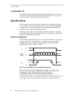
This display requires simultaneous 12V and 5V input in addition to video signals
for proper operation. It is important that your design provides these signals
simultaneously. If these signals are not simultaneous, they must meet the
sequential timing shown in Figure 1 below.

Figure 1. Power Supply and Logic Signal Sequencing

Note: To ensure the long-term reliability of the display, the proper power-
up sequence must be used and the minimum and maximum
specifications in this manual should be met without exception.

All internal high voltages are generated from the display supply voltage (V

H

). The

logic supply voltage (V

L

) should be present whenever video input signals or

VH

12V

0V

VL

5V

0V

0V

Logic
Signals

t

1

0

t

2

0

t

1

0

t

2


0

Summary of Contents for ICEBrite EL Display EL552.256-Q2

Page 1: ...Operations Manual EL552 256 Q2 ICEBRITE TM EL DISPLAY The Definition of Quality ...

Page 2: ... and ColorBrite are trademarks of Planar Systems Inc This document is subject to change without notice Planar provides this information as reference only and does not imply any recommendation or endorsement of other vendor s products Revision Control Date Description October 1998 Document number OM410 00 ...

Page 3: ...erformance 10 Mechanical Specifications 11 Component Envelope 11 Description of Warranty 13 Ordering Information 13 Support and Service 13 Figures Figure 1 Power Supply and Logic Signal Sequencing 4 Figure 2 Connectors 5 Figure 3 Video Input Timing Diagram 7 Figure 4 Pixel Location vs Sequence of Data 8 Figure 5 Display Dimensions 12 Tables Table 1 Video and DC Input Voltage Requirements 5 Table 2...

Page 4: ...iminating the blooming common to other high bright displays The 4 bit LCD type interface is TTL compatible and is designed for hardware compatibility with the SMOS 1353 or equivalent LCD controller Each of the 141 312 pixels has an aspect ratio of 1 1 and is individually addressable to clearly display high information content graphics and text Features Excellent visual performance High brightness ...

Page 5: ...d display Use standoffs of appropriate length to assure that screws through the mounting tabs do not introduce bending stresses to the display Do not deflect the ECB out of its normal plane The EL552 256 Q2 mounting tabs were designed for a 3 mm screw The EL552 256 Q2 NE display does not have mounting tabs Contact Planar Applications Engineering for information on mounting the EL552 256 Q2 NE disp...

Page 6: ...d input voltage unless otherwise specified Planar does not recommend operation of the display outside these specifications Power up Sequence This display requires simultaneous 12V and 5V input in addition to video signals for proper operation It is important that your design provides these signals simultaneously If these signals are not simultaneous they must meet the sequential timing shown in Fi...

Page 7: ... is 1K Ω Connector The EL552 256 Q2 display package includes a DC DC converter and a cable for connecting it to the display As shown in Figure 2 the display is connected to the converter Connector J1 to J3 with the supplied cable then the converter has a connector Connector J0 for interfacing with the customer design Connectors JO T B Ansley 609 1630 J3 T B Ansley 609 2630 J1 T B Ansley 609 2030 F...

Page 8: ... current max IH max 0 9 A Input voltage nom 5 0 V VL 4 75 5 25 VDC Input voltage absolute max VI max 7 5 VDC Input Current max IL max 0 1 A 12V Only Input Description Name Min Max Units Input voltage nom 12 0 V VH 10 8 13 2 VDC Input voltage absolute max VH max 15 0 VDC Input current max IH max 1 0 A Interface Information This Planar EL display incorporates an interface that is similar to many LCD...

Page 9: ... controllers such as the SMOS and C T display controllers Table 4 Video Input Descriptions Num Description Symbol Min Typ Max Units 1 HS high time tHSh 20 nsec 2 HS hold after VCLK tHShd 20 nsec 3 HS setup to VCLK tHSsu 20 nsec 4 VID setup to VCLK tVIDsu 20 nsec 5 VID hold from VCLK tVIDhd 20 nsec 6 Video clock period tVCLK 100 nsec VCLK rise fall time tVCLKrf 15 nsec 7 VCLK low width tVCLKl 15 ns...

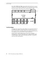
Page 10: ...w 1 Figure 4 Pixel Location vs Sequence of Data Self Test Mode The display will enter the self test mode if all seven video inputs VCLK HS VS and VID0 through VID3 are high for longer then 2 5 seconds at power up The self test scans at 100 Hz with a diagonal pattern that changes back and forth every 2 5 seconds from 3 pixels on 1 pixel off to 1 pixel on 3 pixels off After the self test turn the di...

Page 11: ... may benefit by using grayscales The Q2 has a maximum frame rate frequency of 120 Hz Using the higher frame rate combined with flat panel controllers designed for this faster display it is possible to generate usable grays through frame rate control and dithering Video controllers from manufacturers such as C T SMOS and Cirrus Logic use these methods with proprietary algorithms to generate graysca...

Page 12: ...hocks on each of 6 surfaces per IEC 68 2 27 test Ea The EL display will function at operating survival temperatures 20 to 70 C for a 24 hour period and incur no damage but may not meet some specifications above the 65 C operating limit Reliability The display mean time between failure MTBF is demonstrated to be greater than 30 000 hours at 25 C ambient with a 90 confidence level Safety and EMI Per...

Page 13: ...es Width Height 0 203 0 008 0 203 0 008 Pixel Pitch millimeters inches Width Height 0 264 0 0104 0 264 0 0104 Without DC DC Converter Component Envelope The component envelope shown in Figure 5 illustrates the distance components extend behind the display Tall components do not necessarily fill this area Planar reserves the right to relocate components within the constraints of the component envel...

Page 14: ...in brackets Dimensions of the DC DC Converter are in inches millimeters in brackets Some hidden lines are omitted for clarity Figure 5 Display Dimensions Note The dimensions in this drawing are approximate Please contact Planar Applications Engineering to request the actual drawing prior to beginning your design ...

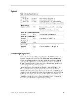
Page 15: ... modification of the goods operation of the goods outside their environmental specifications neglect or abuse of the goods or modification or integration with other goods not covered by a Planar warranty when such modification or integration increases the likelihood of damage of the goods Ordering Information Product Part Number Description EL552 256 Q2 996 0245 02 EL552 256 Q2 ICEBrite display op...

Page 16: ...sales planar com app_eng planar com Planar Systems Inc P O Box 46 Olarinluoma 9 FIN 02201 Espoo Finland Tel 358 9 42 0010 Fax 358 9 422 143 intlsales planar com tech_support planar com Planar Advance Inc P O Box 4001 13950 Karl Braun Drive Beaverton OR 97076 4001 Tel 503 614 4111 Fax 503 614 4101 display_solutions planar com Visit the Planar website at http www planar com for Application Notes and...

Reviews: