EL480.240-PR2/PR3 Users Manual
6
Specifications
The EL panel is a matrix structure with column and row electrodes arranged in
an X-Y formation. Light is emitted when an AC voltage of sufficient amplitude
is applied at a row-column intersection. The display operation is based on the
symmetric, line-at-a-time data addressing scheme.
Power
This display requires both 12V and 5V in addition to video signals for proper
operation. The display is designed to accept simultaneous application of V
L
, V
H
,
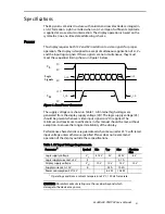
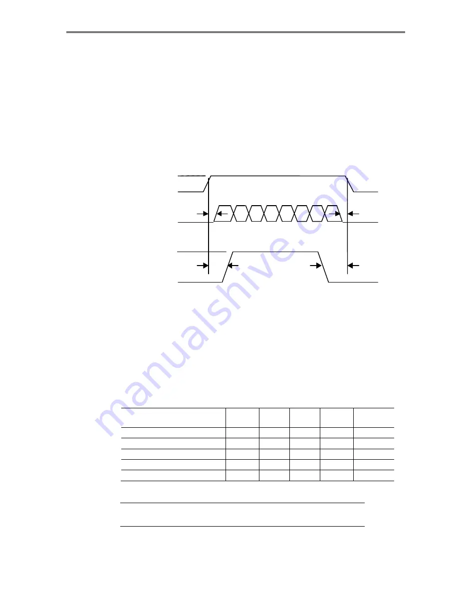
and the input logic signals. If these signals are not simultaneous, they must
meet the sequential timing shown in Figure 1 below.
Figure 1. Data/Power Connector
The supply voltages are shown in Table 1. All internal high voltages are
generated from the display supply voltage (VH). The logic supply voltage (VL)
should be present whenever video input signals or VH is applied. The
minimum and maximum specifications in this manual should be met, without
exception, to ensure the long-term reliability of the display.
Performance characteristics are guaranteed when measured at 25
q
C with rated
input voltage unless otherwise specified. Planar does not recommend
operation of the display outside these specifications.
Table 1. DC Input Voltage Requirements.
Parameter
1
Symbol
Min
Typ
Max
Absolute
Max
Logic supply voltage
V
L
4.75 V
5 V
5.25 V
6 V
Logic supply current at +5 V
I
L
0.1 A
Display supply voltage
V
H
10 V
12 V
15 V
15 V
Supply current at +10 V
I
H
0.5 A
1.05 A
Power consumption 5 V/12 V
6.5 W
10.5 W
1
Operating conditions: ambient temperature 25
q
C, 120 Hz frame rate.
CAUTION: Absolute maximum ratings are those values beyond which
damage to the device may occur.
V H
12V
0V
V L
5V
0V
0V
Logic
Signals
t
1
t
0
t
2
t
0
t
1
t
0
t
2
t
0

