EL480.240-PR2/PR3 Users Manual
7
Table 2. Video Input Requirements.
Description
Min
Max
Units
Notes
Absolute Input Voltage
Range
-0.3
5.5
V
V
L=
5.0 V
Video logic high voltage
70% 100%
V
L
All input thresholds are
CMOS
Video logic low voltage
0
20%
V
L
Video logic input current
–
r
10
µA
Input capacitance
–
15
pF
There is a fuse on the VH input to protect against catastrophic faults, and no
overcurrent protection on the VL input.
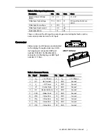
Connector
Video signals and DC power are connected
to the display through a dual-row, 0.050-
inch square-pin connector: AMP part
number 104549-2. For flexible cable
connection to the display, use AMP part
number 111196-4.
Table 3. Connector Pinouts.
Pin
Signal
Description
Pin
Signal
Description
1
V
H
+12 V Power
2
V
H
+12 V Power
3
NC
No Connect
4
GND
Ground
5
V
L
+5 V Power
6
GND
Ground
7
VS
Vertical Sync
8
GND
Ground
9
HS
Horizontal Sync
10
GND
Ground
11
VCLK
Video Clock
12
GND
Ground
13
VID
0
Video Data
14
GND
Ground
15
VID
1
Video Data
16
GND
Ground
17
VID
2
Video Data
18
GND
Ground
19
VID
3
Video Data
20
GND
Ground
AMP 104549-2

