background image

LA1710R, LA1710RTR , LA1710RTS and LA1710RTC User’s Guide  (020-0320-03 Rev. A

)


7

Touch Screen for LA1710RTC

Capacitive for fi nger interface


  Surface: Anti-glare treatment


 Interface: USB


  Durability: 225 million touches in a single location


  Hardness: Cannot be scratched using any stylus with Mohs’  rating of 

                 less than 6.5


 Transmissivity: 88%


  Driver:  Windows® XP, Vista, Windows® 7, Linux

Summary of Contents for LA1710R

Page 1: ...LA1710R LA1710RTR LA1710RTS and LA1710RTC USER S GUIDE www planar com...

Page 2: ...ropean market after July 1 2006 must be compliant with its requirements Planar Systems Inc is fully in support of and compliant with EU Directive 2002 95 EC for applicable products within its scope A...

Page 3: ...Introduction About the Product 5 Package Overview 8 Installation Product Overview 9 User Controls Front Panel Controls 13 How to Use the OSD Menus 14 On Screen Display Menus 15 Appendix Troubleshooti...

Page 4: ...apter that comes with your monitor Disconnect the power plug from AC outlet if the product is not used for an extended period of time Don t Do not touch the LCD display screen surface with sharp or ha...

Page 5: ...Analog VGA and Digital DVI D Active matrix TFT LCD technology 1280 x 1024 SXGA resolution 17 viewable display area 31 80 kHz horizontal scan 56 75 Hz refresh rate 0 264mm x 0 264mm pixel pitch 350 cd...

Page 6: ...y 76 typ Haze 5 Clarity 80 Driver Windows 7 Vista XP 2000 ME 98 NT 4 0 CE XP Embedded Apple Mac OS Linux Touch Screen for LA1710RTS Surface Acoustic Wave SAW touch screen for finger and stylus input S...

Page 7: ...reen for LA1710RTC Capacitive for finger interface Surface Anti glare treatment Interface USB Durability 225 million touches in a single location Hardness Cannot be scratched using any stylus with Moh...

Page 8: ...and LA1710RTC User s Guide 020 0320 03 Rev A Package Overview VGA Signal Cable USB Cable for LA1710RTR LA1710RTC Power Adapter Landing Strip Power Cord DVI Signal Cable L Bracket 2 pcs LCD Display RS...

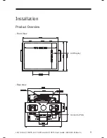
Page 9: ...LA1710R LA1710RTR LA1710RTS and LA1710RTC User s Guide 020 0320 03 Rev A 9 Installation Product Overview Front View Rear View LCD Display Connector Ports...

Page 10: ...10 LA1710R LA1710RTR LA1710RTS and LA1710RTC User s Guide 020 0320 03 Rev A Connector Ports for LA1710RTS only...

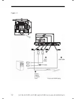
Page 11: ...connector to the 15 pin connector of your host computer and tighten the screws 2 4 For DVI D output connect DVI cable from display to the PC 2a 5 For the LA1710RTR LA1710RTS or the LA1710RTC touch scr...

Page 12: ...12 LA1710R LA1710RTR LA1710RTS and LA1710RTC User s Guide 020 0320 03 Rev A Figure 1 1 4 For LA1710RTS only...

Page 13: ...Adjustment function to obtain an optimum image Brightness Minus Minus 1 Decreases the brightness of the display image 2 Decreases value of the adjustment items Brightness Plus Plus 1 Increases the br...

Page 14: ...he Menu button to pop up the on screen menu and to select between the four main menus 2 Choose the adjustment items by pressing the Select Auto button 3 Adjust the value of the adjustment items by pre...

Page 15: ...and black shades Horizontal Position Changes the horizontal position of the image Vertical Position Changes the vertical position of the image Clock Changes the display data frequency to match the fr...

Page 16: ...s function to view the display resolution vertical refresh and horizontal scan of the current mode OSD Off Time Adjusts the time it takes for the OSD menu to disappear Language Choose the language you...

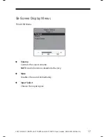
Page 17: ...LA1710RTC User s Guide 020 0320 03 Rev A 17 On Screen Display Menus Third OSD Menu Volume Controls the sound volume NOTE Audio functions disabled at factory Mute Disables the sound immediately Input...

Page 18: ...03 Rev A On Screen Display Menus Fourth OSD Menu Color Adjusts the color temperature Color Adjustment Red Adjusts the red color of the display Color Adjustment Green Adjusts the green color of the di...

Page 19: ...image or incorrectly displayed image Check to see if the resolution of your computer is higher than that of the LCD display Reconfigure the resolution of your computer to make it less than or equal to...

Page 20: ...been powered on but it cannot receive any signal from the computer graphic card Check all the power switches power cables and VGA signal cable Going to Sleep This message means that the LCD display is...

Page 21: ...LA1710R LA1710RTR LA1710RTS and LA1710RTC User s Guide 020 0320 03 Rev A 21 Product Dimensions LA1710R LA1710RTR LA1710RTS and LA1710RTC Front View...

Page 22: ...22 LA1710R LA1710RTR LA1710RTS and LA1710RTC User s Guide 020 0320 03 Rev A LA1710R non touch LA1710RTR resistive touch LA1710RTC capacitive touch LA1710R LA1710RTR LA1710RTS and LA1710RTC Side View...

Page 23: ...LA1710R LA1710RTR LA1710RTS and LA1710RTC User s Guide 020 0320 03 Rev A 23 LA1710R LA1710RTR LA1710RTS and LA1710RTC Rear View...

Page 24: ...s The monitor supports the following industry standard combinations of screen resolution and refresh rates Other combinations are possible but may require adjustments to the image For the optimal perf...

Page 25: ...ot automatically load restart the computer operating system Please read Readme txt located in the unzipped file folder for additional information and assistance Linux Driver Installation for LA1710RTC...

Page 26: ...nstall section for more information LA1710RTR Optional Calibration Tool Install If you would like to use the Optional Calibration Tool follow the instructions below Please note the calibration tool su...

Page 27: ...is disabled click on the XP driver at www planar com support and follow the step by step instructions as shown on the pop up windows Custom 1 Power on the computer 2 Make sure that the USB cable is co...

Page 28: ...ion Tool Install section for more information LA1710RTS Optional Calibration Tool Install If you would like to use the Optional Calibration Tool follow the instructions below Please note the calibrati...

Page 29: ...is disabled click on the XP driver at www planar com support and follow the step by step instructions as shown on the pop up windows Custom 1 Power on the computer 2 Make sure that the RS232 or USB c...

Page 30: ...he computer 3 Remove the original Touch Interface RS 232 or USB 4 Connect the computer to the Touch Interface RS 232 or USB that you would like to use 5 Load the touch driver found at www planar com s...

Page 31: ...s manuals line drawings touch screen drivers warranty information and access to Planar s Technical Library for online troubleshooting To speak with Planar Customer Support please have your model and s...

Page 32: ...m 8pm Eastern Time M F 5am 5pm Pacific Time Europe and Asia Pacific Support Tel 358 9 420 01 Hours M F 7am 4pm CET 2011 Planar Systems Inc 05 11 Planar is a registered trademark of Planar Systems Inc...

Reviews: