background image


LC1200R User’s Guide


  021-0183-00 Rev A  


17 of  29 

The LC1200R is not damaged by input voltages ranging from 0-vdc to 12.4-vdc. 

5.3


Power On-Off Sequences 

The LC1200R will automatically return to normal operation upon resumption of power after a power 
loss. 

6


User Controls 

6.1


LCD Controller Board Controls 

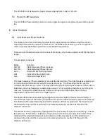
The display comes from the factory adjusted for the supported modes. When using these modes, 
adjustment should not be necessary. However, if it should become necessary, or a non-supported 
mode is selected, the following controls are available for adjustment. 

There are 4 push buttons located on the back of the display, which allow adjustment of the displayed 
image.   

The provided controls are:                      

Name 

  Function 

Dot Clk - 

  Clock Frequency/Phase Decrease  

Dot Clk + 

  Clock Frequency/Phase Increase 

Horiz 

  Horizontal Position Adjustment 

Vert 

  Vertical Position Adjustment 

Gain 

  Video Gain Adjustment 

The Clock Frequency /Phase adjustments are dual function buttons. The clock frequency adjustment 
is used to change the horizontal size of the displayed image.   The Phase adjustment is used to 
minimize the pixel ‘noise’ or ‘jitter’.  The phase allows for 32 positions of phase control. If the button is 
held down, the clock frequency is adjusted up or down 1 clock each time the phase control register 
rolls over. To adjust the clock frequency further, continue to hold the button down. If phase 
adjustment is desired, it’s best to use single presses. 

The Horizontal Position is adjusted by holding down the Horiz button. The position will shift by 1 
column for each press. If the button is held down, the position will continuously adjust until released. 
The direction of the adjustment depends on the direction of the last adjustment. The direction will 
continue to be true until the maximum or minimum adjustment is reached. At this point, the 
direction will reverse. 

The Vertical Position is adjusted by holding down the Vert button. The position will shift by 1 column 
for each press. If the button is held down, the position will continuously adjust until released. The 
direction of the adjustment depends on the direction of the last adjustment. The direction will 
continue to be true until the maximum or minimum adjustment is reached. At this point, the 
direction will reverse 

Summary of Contents for LC1200R

Page 1: ...LC1200R High Bright Monitor USER S MANUAL www planar com ...

Page 2: ...nd Humidity 9 3 2 Direct Sunlight Operation 10 3 3 Altitude 10 3 4 Mechanical Vibration and Shock 10 4 VIDEO SIGNAL REQUIREMENTS 11 4 1 Video Input Lines 11 4 2 Signal Functions 11 4 3 Signal Quality 14 4 4 Timing and Frequency 15 4 5 Video Signal On Off Sequences 15 5 DC POWER INPUT REQUIREMENTS 16 5 1 DC Power Input Lines 16 5 2 DC Input Voltage Current 16 5 3 Power On Off Sequences 17 6 USER CO...

Page 3: ...te Display Picture Mode 24 9 REGULATORY AGENCY REQUIREMENTS 24 9 1 Safety Certification 24 9 2 CE Marketing 24 9 3 RFI Emission Certification 25 9 4 System Transient Disturbance Requirements 25 9 5 Labeling 25 9 6 ROHS Compliance 26 10 RELIABILITY 26 10 1 Design Workload 26 10 2 MTBF 26 11 DESCRIPTION OF WARRANTY 26 12 SUPPORT AND SERVICE 27 13 GLOSSARY OF TERMS 28 ...

Page 4: ...ght backlight inverter board and LCD controller board A tethered photodiode provides automatic brightness control Cooling fans are provided to cool the back of the LCD module If used in direct sunlight it is the system designer s responsibility to provide an enclosure that directs the airflow across the front of the display Two 2 chassis mounted connectors at the rear provide for video signal and ...

Page 5: ...omatically program itself sensing incoming horizontal vertical frequencies and sync pulse polarities to completely fill the active display area of the LC1200R with the video resolution being presented Section 4 2 defines parameters for video resolution detection by the LCD controller board Note IBM VGA1 modes with border and the 720 x 400 video resolutions are excluded from completely filling the ...

Page 6: ...es Removable Button Board Door to User control Connectors 185 08 57 5 4X Fan inlet B A Front View Rear View Right View Center 185 Active Area 123 Active area 301 152 15 246 Active area 63 235 Top of removable 83 standoff 4X M3 mnt holes VGA Conn Power 12 V 4X M3 mnt holes ...

Page 7: ...put Connector The DC power input connector is a chassis mounted 2 pin connector Molex Mini Fit Jr Header 5569 Molex p n 39 30 0020 with pin contacts at the side of the LC1200R The connections are insulated to prevent accidental contact 2 5 3 Photodiode Connector A 3 pin connector Molex p n 22 03 5035 is provided on the inverter board The connector accepts the cable assembly provided with the produ...

Page 8: ...nimizing aliasing and image distortion The LCD controller board includes the following characteristics Per pixel scaleable filters providing text sharpening and graphics smoothing for improved image quality Color depth enhancement by performing spatial temporal dithering reducing visual artifacts External controls See User Controls Page 18 for more information There are 5 connectors for 12 V fans ...

Page 9: ... Humidity Humidity Humidity Humidity Note 1 Note 1 Without Condensation Tair is defined as ambient air temperature surrounding the LC1200R Note 1 Tair 32 C 95 RH maximum Tair 32 C Absolute humidity content not to exceed 100 at 32oC Note 2 Tair 20 C 48 hours Tair 60 C 168 hours Note 3 Slight background color changes are allowed depending on ambient temperature This phenomenon is reversible Note 4 H...

Page 10: ...3 4 1 Vibration Non operating sinusoidal 10 200 Hz 0 9g acceleration 120 seconds per sweep for 15 minutes three axes x y z Following exposure unit shall meet all performance requirements Non operating random 10 200 Hz 0 02g2 Hz 10 min axis three x y z Following exposure unit shall meet all performance requirements 3 4 2 Shock Non operating 30 g 2 5 ms duration sine 1 shocks per axis Following expo...

Page 11: ...ector Pin Number Assignments Pin Number Assignments Pin Number Assignments Pin Number Assignments Pin Number Pin Number Pin Number Pin Number Signal Name Signal Name Signal Name Signal Name 1 Red Video 2 Green Video 3 Blue Video 4 Monitor Sense Line 3 connected to Pin 10 5 NC 6 Red video return 7 Green video return 8 Blue video return 9 NC 1 0 Signal Ground Reference 1 1 Monitor Sense Line 1 conne...

Page 12: ... analog input The LC1200R is capable of resolving a minimum color range of 262 144 displayable colors 6 bit resolution for red green and blue This interpolates to 64 shades of gray or color at the red green and blue analog video inputs Accomplishing specified shades of gray requires a Video Gain control adjustment Section 6 1 of red green and blue analog input signals based on the maximum output l...

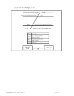
Page 13: ...LC1200R User s Guide 021 0183 00 Rev A 13 of 29 Figure 4 TTL Allowable Signal Levels ...

Page 14: ...8 70 VESA 800 x 600 48 077 72 VESA 1024 x 768 56 48 70 4 2 4 Color Display Detection The video signal source determines which type of display is connected to it based on the state of the LC1200R sense lines The LC1200R will indicate to the source that it is a color display when the monitor sense line 1 Pin 11 is physically connected to signal ground reference Pin 10 as defined by the wiring defini...

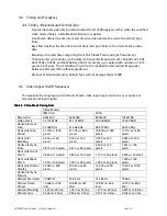
Page 15: ...Table Table Table 6 6 6 6 Video Mode Timing Data Video Mode Timing Data Video Mode Timing Data Video Mode Timing Data Video Modes IBM VGA VESA Resolution 640x400 640x480 800x600 1024x768 Video Clock 25 175 MHz 25 175 MHz 50 000 MHz 75 000 MHz Horizontal Scan Freq 31 468 KHz 31 468 KHz 48 077 KHz 56 476 KHz Horizontal Line Period 31 778 us 800 pixels 31 778 us 800 pixels 20 800 us 1040 pixels 17 70...

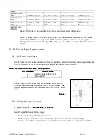
Page 16: ...and supplied attached to the LC1200R as a chassis mounted connector per definitions listed in Table 7 Table Table Table Table 7 7 7 7 DC Power Input Connector DC Power Input Connector DC Power Input Connector DC Power Input Connector Pin Assignments Pin Assignments Pin Assignments Pin Assignments PIN NUMBER PIN NUMBER PIN NUMBER PIN NUMBER SIGNAL NAME SIGNAL NAME SIGNAL NAME SIGNAL NAME 1 Positive...

Page 17: ...he displayed image The Phase adjustment is used to minimize the pixel noise or jitter The phase allows for 32 positions of phase control If the button is held down the clock frequency is adjusted up or down 1 clock each time the phase control register rolls over To adjust the clock frequency further continue to hold the button down If phase adjustment is desired it s best to use single presses The...

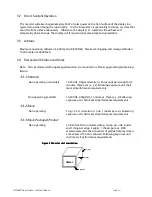
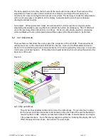
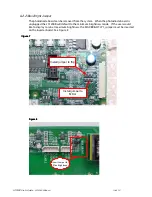
Page 18: ... pixels along all four edges while the auto adjust is performed 6 2 User Adjustments There are features that allow the user to adjust the properties of the LC1200R These adjustments will require access to the video board PCB and the inverter Access to the Photodiode Connector Section 2 5 3 and Dimming Control Connector Section 2 5 4 can be gained by removing 1 screw and a small access panel See Fi...

Page 19: ...plugged the LC1200R will default to the minimum brightness mode If the user would like to display to run at maximum brightness the MAX BRIGHT JP1 jumper must be inserted on the inverter board See Figure 8 Figure Figure Figure Figure 7 7 7 7 Install jumper to flip Install jumper to Mirror Figure Figure Figure Figure 8 8 8 8 Insert Jumper for Max Brightness ...

Page 20: ...s where an external potentiometer is used to generate the DIM input If used a 50k potentiometer is recommended Any connection made to the DIM input will override the Automatic dimming function thus leave the DIM input open if using the photodiode for automatic dimming Connector mates with Molex 5264 and 42219 series Connector Pin Assignments Table Table Table Table 9 9 9 9 Pin Pin Pin Pin Name Nam...

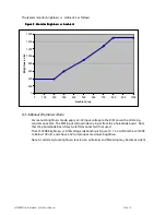
Page 21: ...ltage to the DIM pin on the dimming control connector The DIM input will override any input from the photodiode board Note that the photodiode board may be left disconnected if not used The LC1200R brightness vs DIM voltage relationship is Figure 10 1 5V will dim the LC1200R to below 100 nits and above 3 5V will produce maximum brightness Note At extremely low brightness levels non uniformity and ...

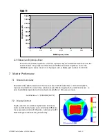
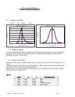
Page 22: ...inch jumper such as Molex part number 15 29 1024 7 Monitor Performance 7 1 Monitor Luminance Minimum white light luminance at the screen center of the Monitor face is 1500 cd m2 467 fL measured normal to the screen face Luminance specification applies to the initial luminance i e prior to additional operation in the end system and after a 10 minute warm up Luminancemin 1 500cd m2 467 fL 7 2 Displa...

Page 23: ...e normal to the screen face 7 4 Display Chromaticity The metric used for color coordinate determination is the CIE 1976 UCS Uniform Chromaticity Scale u v system Color determination is performed normal to the display in a dark room environment with ambient light conditions less than 10 lux 1fC incident illumination The measured u v color coordinates at room temperature for white light and the red ...

Page 24: ...is acceptable if there are 4 or less black dots visible from 35c 14in with the unaided eye The LCD panel is acceptable if no more than 3 dots are joined 9 Regulatory Agency Requirements 9 1 Safety Certification The LC1200R does not inhibit customer from certifying product to the following safety standards UL 1950 CAN CSA C22 2 No 950 95 Safety of Information Technology including electrical busines...

Page 25: ...f information technology equipment IEC 1000 3 2 1995 EN 61000 3 2 Current Harmonic Tests IEC 1000 3 3 1995 EN 61000 3 3 Voltage Fluctuation and Flicker Test 9 4 System Transient Disturbance Requirements The LC1200R meets the following system transient disturbance requirements 9 4 1 Electrostatic Discharge The LC1200R performs normally when subjected to static electricity discharges from persons to...

Page 26: ...orescent backlight assembly The LC1200R MTBF is TBD hours 11 Description of Warranty Seller warrants that the Goods will conform to published specifications and be free from defects in material for 12 months from delivery To the extent that Goods incorporate third party owned software Seller shall pass on Seller s licensor s warranty to Buyer subject to the terms and conditions of Seller s license...

Page 27: ...either modify the warranty nor create an obligation of Seller Buyer is not relying on Seller s skill or judgment to select Goods for Buyer s purposes Seller s software if included with Goods is sold as is and this warranty is inapplicable to such software SELLER DISCLAIMS ALL OTHER WARRANTIES EXPRESS OR IMPLIED INCLUDING BUT NOT LIMITED TO IMPLIED WARRANTIES OF MERCHANTABILITY AND FITNESS FOR A PA...

Page 28: ...color also called a tristimulus value The unit value of each component is the amount of that component added to the other two components to produce a reference white Color Saturation A psycho physiological measurement of the degree to which a color appears to be free of white light Color Temperature The temperature to which a black body must be heated to produce a color matching that of the source...

Page 29: ...ometer Any optical device which uses a comparison technique to measure luminous intensity luminance or illumination An equality of brightness photometer is based on simultaneous comparison of adjoining visual areas a flicker photometer compares successive stimuli in the same visual area Resolution The number of addressable controllable display or picture elements or the number of hypothetical coor...

Reviews: