LC640.480.21-065 Operations Manual (OM610-00)
20
Luminance Features
Backlight Dimming
Control for backlight dimming is performed by several methods depending on how the
switches on switch block SW1 (see Figure 9) are set as shown in Table 14 below. These
selections are available for both standard and controlled luminance mode.
Table 14. Backlight Dimming Control.
Luminance Control
Switch
1
Switch
2
Switch
3
Manual control
off
off
–
Automatic control with ambient light sensor
on
off
–
Automatic control with manual offset and
ambient light sensor
off
on
–
Note: Because Switch 3 is not used, its position has no effect.
Manual Dimming
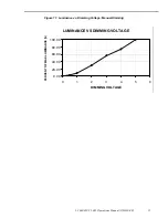
This mode allows the user to adjust the luminance by varying the input from 0 to +5 Vdc
on pin 33 (DIM) of the video input connector (J1). See Figures 10 and 11.
Table 15. Manual Dimming Specifications.
Description
Specification
Dimming range
Approximately 300:1
Analog voltage input (DIM)
Compatible with voltage and potentiometer (3 terminal)
No connection results in maximum luminance
Voltage range: 0 to +5V (+5V equals maximum luminance)
Dimming method
Pulse width modulation (period = 100 millisecond, 256
discrete steps, linear)
Recommended pot value
10K ohm
DIM REF
High side pot reference output provided, short-circuit
protected
SWI Setting
Switch 1 = OFF, Switch 2 = OFF
Figure 10. Dimming Voltage Input on J1 (DIM).
DIMREF
(PIN 34)
GND
(PIN 36)
DIM
(PIN 33)
ON
ON
ON

