LC640.480.21-065 Operations Manual (OM610-00)
28
Cell Heater (Optional version 996-0406-01)
The cell heater consists of a glass panel with an ITO coating on one side. There are bus
bars along each side of the panel. The heater decreases the response time of the AMLCD
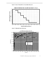
cell at low temperatures by heating the liquid crystal material in the cell. Figure 18
shows the response time performance at different heater voltages.
If the temperature is below +10
°
C, the ITO heater is turned on at 100% duty cycle for
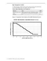
the time shown in Figure 19 on page 29. The heater duty cycle is then set as shown in
Figure 20 on page 29.
Table 21. Cell Heater Parameters.
Parameter
Value
Units
Type
Resistive: ITO on glass (~ 7.5 ohms/square)
Total resistance ~ 12 ohms
None
Active temperature sensor
Monitor temperature sensor with the highest reading
None
Control
Duty cycle is stepped as shown in Figure 21
%
Trip point
Not applicable
C
Hysteresis
3.0
C
Heater voltage
8-18
Vdc
Power
5.3 (@ 8 V), 27 (@18V)
Watts
Figure 18. Cell Heater Response Time Performance.
DISPLAY RESPONSE TIME VS TIME
(with cell heater, ambient temperature = -40C, Vdim=2.5)
0
100
200
300
400
500
600
700
800
900
1000
1100
1200
1300
1400
1500
1600
1700
1800
0
2
4
6
8
10
12
14
16
18
TIME (minutes)
RESPONSE
T
IM
E
(m
illisec
onds)
cell heater voltage = 0.0
cell heater voltage = 8.0
cell heater voltage = 12.0
cell heater voltage = 18.0


