background image


 22  

 
APPENDIX (cont.) 


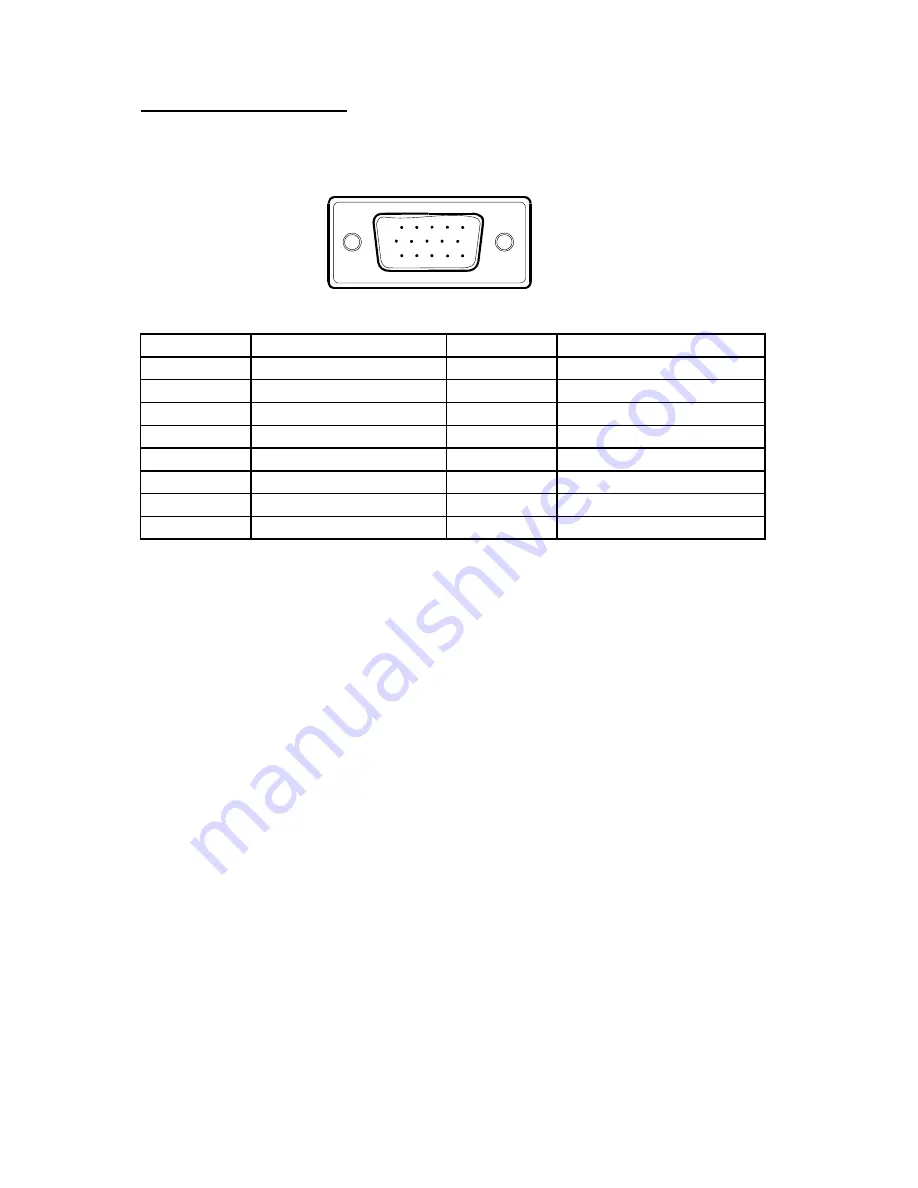
Connector Pin Assignment 
 

1

5

6

10

11

15


15 - Pin Color Display Signal Cable 


PIN NO. 

DESCRIPTION 

PI N NO. 

DESCRIPTION 

1. 

Video-Red 

  9. 

+5V 

2. Video-Green 

10. 

Detect 

Cable 

3. Video-Blue 

11. 

NC 

4. NC  12. 

DDC-Serial 

data 

5. Ground 

13. 

H-sync 

6. GND-R 

14. 

V-sync 

7. GND-G 

15. 

DDC-Serial 

clock 

8. GND-B 


Summary of Contents for PE2010

Page 1: ...PE2010 ...

Page 2: ... documentation view answers to frequently asked questions FAQs and get troubleshooting advice or email Planar your support question Talk to a Customer Service Representative To contact Planar s Customer First TM Technical Support Service call 1 866 PLANAR 1 866 752 6271 This service is available 5am 5pm Pacific Time 8am 8pm Eastern Time Monday through Friday Contact Us 24x7 Online Technical Suppor...

Page 3: ...ights are reserved No part of this document may be reproduced translated to another language or stored in a retrieval system or transmitted by any means electronic mechanical photocopying recording or otherwise without prior written permission Windows is a registered trademark of Microsoft Inc Other brand or product names are trademarks of their respective holders ...

Page 4: ...ents of the package 8 Installation Instructions Power source 9 Connecting the cables 10 Adjusting the viewing angle 11 Operating Instructions External controls 12 How to adjust a setting 14 Adjusting the picture 15 Technical Support FAQ Technical Support FAQ 17 Error message possible solution 18 Appendix Specifications 19 Preset display modes 21 Connector pin assignment 22 ...

Page 5: ...n between the equipment and receiver 3 Connect the equipment into an outlet on a circuit different from that to which the receiver is connected 4 Consult the dealer or an experienced radio TV technician for help NOTICE 1 The changes or modifications not expressly approved by the party responsible for compliance could void the user s authority to operate the equipment 2 Shielded interface cables an...

Page 6: ... source indicated on the label If you are not sure of the type of power supplied to your home consult your dealer or local power company z The monitor is equipped with a three pronged grounded plug a plug with a third grounding pin This plug will fit only into a grounded power outlet as a safety feature If your outlet does not accommodate the three wire plug have an electrician install the correct...

Page 7: ...on below it s native resolution which may slightly degrage the display quality Therefore it is highly recommended to operate the monitor at it s native resolution of 1400 x 1050 60Hz OTHER NOTES The screen surface is very soft Do not rub touch or tap the screen surface with sharp object such as pen or pencil This contact may scratch or damage the screen These damages are not covered under the warr...

Page 8: ...play capabilities The communication channel is defined in two levels DDC1 and DDC2B The DDC1 is a unidirectional data channel from the display to the host that continuously transmits EDID information The DDC2B is a bidirectional data channel based on the I C protocol The host can request EDID information over the DDC2B channel This monitor will appear to be non functional if there is not video inp...

Page 9: ... Today Thank you for choosing Planar To assure you receive all the benefits of your Planar product and services register your Planar product today Visit our website to register your product at http www planar com support product_registration html Cables Replacement Lamps and Accessories To find cables replacement lamps and accessories for your Planar projector LCD monitor touchscreen or other Plan...

Page 10: ...oride flexible cord according to IEC 60227 designation H05VV F 3G 0 75mm2 or H05VVH2 F2 3G 0 75mm 2 shall be used As an alternate a flexible cord of synthetic rubber according to IEC 60245 designation H05RR F 3G 0 75mm2 shall be used The accessory power cord for the Northern American region is the wall plug with NEMA 5 15 style and is UL listed and CSA labeled The voltage rating for the power cord...

Page 11: ...end to a nearby AC outlet 2 Connect one end of the 15 pin D Sub cable to the back of the monitor and connect the other end to the computer s D Sub port 3 Optional Requires a video card with DVI port Connect one end of the 24 pin DVI cable to the back of the monitor and connect the other end to the computer s DVI port be tightened 4 Turn on your monitor and computer If you monitor diplays an image ...

Page 12: ...our own preference Hold the stand so you do not topple the monitor when you change the monitor s angle You are able to adjust the monitor s angle from 5 to 20 Figure 3 NOTES Do not touch the LCD screen when making the adjustments above It may cause damage or break the LCD screen Careful attention is required not to catch your fingers or hands when making the adjustments above ...

Page 13: ...5 Menu Enter 2 Auto Config Exit 6 Power Indicator 3 ECO changing 7 Power Button 4 Bri con Power Button Press this button to turn the monitor ON or OFF MENU ENTER Active OSD menu or function adjust confirm ECO ECO switching Bri Con Bri Con adjusting Source Select the VGA or DVI function ...

Page 14: ...o Adjustment function is used to set the HPos VPos Clock and Focus Power Indicator Green Power On mode Amber Standby mode Osd Lock Function Option 1 OSD lock all 5 buttons are locked except the POWER button Press and hold the and MENU buttons for 3 seconds to lock the buttons Repeat this step to unlock Option 2 OSD Power button lock all 6 buttons including the POWER button are locked Press and hol...

Page 15: ...ted press the MENU button to activate it If the function selected has a sub menu press or again to navigate through the sub menu functions Once the desired function is highlighted press MENU button to activate it 3 Press or to change the settings of the selected function 4 To exit and save select the exit function If you want to adjust any other function repeat steps 2 3 Figure 5 The OSD Message ...

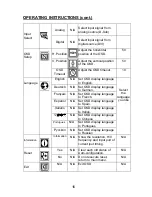
Page 16: ...oise Do Auto Config Image Setup Clock Adjust picture Clock to reduce Vertical Line noise Do Auto Config H Position Adjust the horizontal position of the picture Do Auto Config Image Position V Position Adjust the verticalposition of the picture Do Auto Config C1 N A Recall Warm Temperature from EEPROM C2 N A Recall Warm Temperature from EEPROM sRGB N A Recall sRGB Temperature from EEPROM Red Gain ...

Page 17: ...y language to German Français N A Set OSD display language to French Español N A Set OSD display language to Spain Italiano N A Set OSD display language to Italian 简体中文 N A Set OSD display language to Chinese Portugues N A Set OSD display language to Portugues Language Pyccknn N A Set OSD display language to Russian Select the language you like Information Information N A Show the resolution H V f...

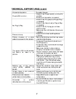
Page 18: ...ON position Computer Video Card should be snugly seated in its slot Make sure monitor s video cable is properly connected to the computer Inspect monitor s video cable and make sure none of the pins are bent Make sure computer is operational by hitting the CAPS LOCK key on the keyboard while observing the CAPS LOCK LED The LED should either turn ON or OFF after hitting the CAPS LOCK key Missing on...

Page 19: ...the picture has horizontal disturbances in light picture For FOCUS and CLOCK adjustment use dot pattern or win 95 98 shut down mode pattern CABLE NOT CONNECTED 1 Check that the signal cable is properly connected If the connector is loose tighten the connector s screws 2 Check the signal cable connection pins for damage INPUT NOT SUPPORT Your computer has been set to unsuitable display mode Set the...

Page 20: ...Max Resolution 1400 x 1050 60Hz Plug Play VESA DDC1 2BTM ON Mode 41 W EPA ENERGY STAR OFF Mode 1W D Sub 15pin Input Connector DVI 24pin Analog 0 7Vp p standard 75 OHM Positive Input Video Signal Digital sigal Maximum Screen Size Horizontal 432 50mm Vertical 332 00mm Power Source 100 240VAC 47 63HZ Environmental Considerations Operating Temp 0 to 35 C Storage Temp 20 to 60 C Operating Humidity 10 t...

Page 21: ...ernal Controls Functions Contrast Brightness Focus Clock H Position V Position Warm Color Cool Color SRGB Color temperature User Input signal Selection OSD position OSD timeout Language Display information Reset Exit Power Consumption Maximum 41 Watts Regulatory Compliance UL cUL FCC B CE ...

Page 22: ...IBM DOS 720 400 31 47 70 0 640 480 31 47 60 0 VGA 640 480 37 50 75 0 800 600 37 879 60 0 SVGA 800 600 46 875 75 0 1024 768 48 363 60 0 1024 768 56 476 70 0 1024 x 768 60 02 75 0 1024 x 768 48 780 60 0 VESA XGA 1024 x 768 60 241 75 0 1280 1024 64 00 60 0 SXGA 1280 1024 80 00 75 0 SGXA 1400 x 1050 75 00 60 0 ...

Page 23: ... 6 10 11 15 15 Pin Color Display Signal Cable PIN NO DESCRIPTION PI N NO DESCRIPTION 1 Video Red 9 5V 2 Video Green 10 Detect Cable 3 Video Blue 11 NC 4 NC 12 DDC Serial data 5 Ground 13 H sync 6 GND R 14 V sync 7 GND G 15 DDC Serial clock 8 GND B ...

Page 24: ...a 2 14 5V Power 3 TMDS Data 2 4 Shield 15 Ground for 5V 4 TMDS Data 4 16 Hot Plug Detect 5 TMDS Data 4 17 TMDS Data 0 6 DDC Clock 18 TMDS Data 0 7 DDC Data 19 TMDS Data 0 5 Shield 8 NC 20 TMDS Data 5 9 TMDS Data 1 21 TMDS Data 5 10 TMDS Data 1 22 TMDS Clock Shield 11 TMDS Data 1 3 Shield 23 TMDS Clock 12 TMDS Data 3 24 TMDS Clock ...

Page 25: ...OR 97006 1992 www planar com 2006 Planar Systems Inc Planar is a registered trademark of Planar Systems Inc Other brands and names are the property of their respective owners Technical information in this document is subject to change without notice ...

Reviews: