6
Interface for Arm Applications
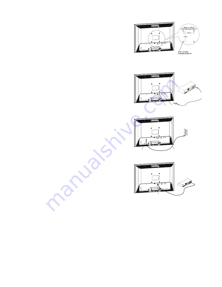
The rear of this LCD display has four integrated 4 mm, 0.7
pitch threaded nuts, as well as four 5 mm access holes in the
plastic covering as illustrated in Figure 1-4. These
specifications meet the VESA Flat Panel Monitor Physical
Mounting Interface Standard (paragraphs 2.1 and 2.1.3,
version 1, dated 13 November 1997).
Note: Please using M 4mm x 16mm (L) screw for this
application.
Figure 1-4
Connecting the Display
1.
Power off your computer.
2.
Connect one end of the signal cable to the LCD Monitor’s
VGA port or DVI port. (See Fig 1-5)
3.
Connect the other end of the signal cable to the VGA port
or DVI port on your PC .
4.
Make sure connections are secure.
Figure1-5
Connecting the AC Power
5.
Connect the power cord to the LCD Monitor.(See Fig. 1-6)
6.
Connect the power cord to an AC power source.
Figure1-6
Connecting the Audio Cable
1.
Connect the audio cable to the "LINE OUT" jack on your
PC's audio card or to the front panel's “AUDIO OUT” jack of
your CD ROM drive. (See Fig. 1-7)
Connect the other end of the audio cable to the LCD Monitor's
"LINE IN" jack.
Figure1-7
Setting Up the LCD Monitor
1. Make sure the
AC power cord is connected to the LCD Monitor.
2. Turn on the LCD Monitor's power switch, located on the bezel of the monitor.
Power Management System
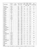
This LCD Monitor complies with the VESA DPM Power Management guidelines. If you have VESA's DPM™
compliance display card or software installed in your PC, the monitor can automatically reduce its
power consumption when not in use. If input from keyboard, mouse or other input devices is detected
by the computer, the monitor will automatically "wake up". When the LCD Monitor is in power saving
mode, the monitor screen will be blank and the power LED indicator will light yellow.
DVI D-SUB
Power Jack
Power Cord
Audio Jack
Summary of Contents for PL1911MW
Page 1: ......
Page 12: ...11 Repeat this step to unlock ...
Page 17: ...16 the display and cannot be expanded to full screen ...
Page 20: ......


