background image


COMMUNIQUE  D’AVERTISSEMENT  DE  LA  FCC  CONCERNANT  LES  INTERFERENCE  DE 

FREQUENCE RADIO: (SEULEMENT POUR MODELES CERTIFIE PAR LA FCC)


Ce moniteur a été testé et à été trouvé conforme aux limites pour un appareil numérique de 

Classe B, suivant la partie 15 des règlements de la FCC. Ces limites ont été développées pour 

offrir une protection satisfaisante contre les interférences nuisibles dans une installation 

résidentielle. Ce moniteur génère, utilise et peut radier de l’énergie de fréquence radio. Ceci 

peut causer des interférences nuisibles à des communication radio si l’appareil n’est pas 

convenablement installé et utilisé. Il n’y à néanmoins aucune garantie que des interférences 

n’apparaîtront pas dans une installation particulière. Si ce moniteur cause de sérieuses 

interférences à la réception de signaux radios ou télévisées, une possibilité est de réinitialiser le 

moniteur. Les usagers sont aussi encouragés à corriger les interférences en appliquant une ou 

plusieurs des démarches suivantes: 


Réorientez ou déplacez l’antenne de réception. 


Placez le moniteur et le récepteur plus loin l’un de l’autre. 


Connectez le moniteur à une prise différente de celle à laquelle le récepteur est connecté.


Consultez votre revendeur local ou un technicien qualifié.


Avertissement de la FCC: 

Pour assurez une conformité continue au règlements de la FCC, l’utilisateur doit utiliser un 

cordon d’alimentation mis à terre et le câble d’interface vidéo protégé avec noyaux en ferrite, 

fourni avec l’appareil. Chaque modification ou changement non-autorisé appliqué à ce moniteur 

peut faire perdre à l’utilisateur sont droit d’opération de cet appareil. 


Note: 

Si nécessaire, des câbles d’interface protégés et un cordon d’alimentation alternante 

doivent être utilisé pour être conforme aux limites d’émission. 
 

Important Waste Disposal Information


Please recycle or dispose of all electronic waste in accordance with local, state, and federal laws. 
Additional resources can be found online at 

http://www.planar.com/about/green/

.


The crossed-out wheelie bin symbol is to notify consumers in areas subject to Waste Electrical and 
Electronic Equipment (WEEE) Directive 2012/19/EU that the product was placed on the market 
after August 13, 2005 and must not be disposed of with other waste. Separate collection and 
recycling of electronic waste at the time of disposal ensures that it is recycled in a manner that 
minimizes impacts to human health and the environment. For more information about the proper 
disposal of electronic waste, please contact your local authority, your household waste disposal 
service, or the seller from whom you purchased the product.


Summary of Contents for PLL2210MW

Page 1: ...www planar com USER S GUIDE LED LCD Monitor PLL2210MW...

Page 2: ...3 First Setup 5 Front View of the Product 6 Rear View of the Product 7 Quick Installation 8 Basic Operation 9 Advanced Operation OSD Menu 11 Supporting Timing Modes 14 Technical Information 15 Wall mo...

Page 3: ...occur in a particular installation If this LED LCD Monitor does cause serious interference to radio or television reception resetting the LED LCD Monitor may determine it Moreover users are encouraged...

Page 4: ...endeur local ou un technicien qualifi Avertissement de la FCC Pour assurez une conformit continue au r glements de la FCC l utilisateur doit utiliser un cordon d alimentation mis terre et le c ble d i...

Page 5: ...time Don t Do not touch the LED Display screen surface with sharp or hard objects Do not use abrasive cleaners waxes or solvents for your cleaning Do not operate the product under the following condit...

Page 6: ...sifs de la cire ou des solvants pour le nettoyage N utilisez pas le produit dans les conditions suivantes o Plus de 16 heures par jour o Environnement extr mement chaud froid ou humide o Endroits pous...

Page 7: ...the monitor from being scratched put a piece of soft cloth on the table on which the screen will be set 2 Unpack the base one hand hold the monitor the other hand attach the base to the stand 3 Stand...

Page 8: ...6 Front View of the Product OSD Turn On Off Brightness Scroll Down Adjust Decrease Blue Light Scroll UP Adjust Increase Input select Confirm Selection Power On Off LED Indicator...

Page 9: ...7 Rear View of the Product Power input 12V DC in DVI Input DVI 24 pin VGA Input D Sub 15 pin Audio Input...

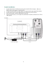
Page 10: ...ble from audio output of computer to the audio input of the monitor 3 Connect the AC power cord to the AC DC power adapter then to the monitor 4 Power ON computer and then POWER ON the monitor 5 Set t...

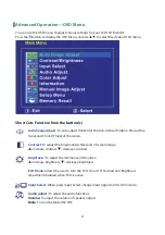
Page 11: ...Selects between VGA DVI or Auto mode Select the desired item when in OSD menu When not in OSD menu directly enters Brightness menu press 3 seconds enters Auto Image Adjust Select the desired item whe...

Page 12: ...cluding the POWER button are locked Press and hold the 1 button and the button for 3 seconds to lock all 5 buttons The LED LCD Monitor will show an Lock Out message for 3 seconds and the message will...

Page 13: ...lock H Size of the screen Contrast To adjust the foreground white level of screen image increase contrast decrease contrast Brightness To adjust the luminance of the video increase brightness decrease...

Page 14: ...reduction Low Light Ideal for low ambient lighting environments 70 reduction Information To display the information regarding the current input signal coming from the graphic card in your computer Not...

Page 15: ...SD Position OSD Time Out and OSD Background Language Select To allow users to choose from available languages OSD Position Press or button to select between horizontal and vertical OSD Position adjust...

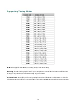
Page 16: ...x 1024 60Hz VESA 1280 x 1024 75Hz VESA 1440 x 900 60Hz CVT 1400 x 1050 60Hz VESA 1600 x 900 60Hz VESA 1600 x 1200 60Hz VESA 1680 x 1050 60Hz VESA 1920 x 1080 60Hz Note DVI supports 480i 480p 576i 576...

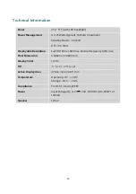
Page 17: ...t Displayable Resolution Full HD 1920 x 1080 max Vertical Frequency 60Hz max Pixel Dimension 0 24825 x 0 24825 mm Display Color 16 7M Tilt 5 2 20 2 Active Display Area 476 64 mm x 268 11 mm Temperatur...

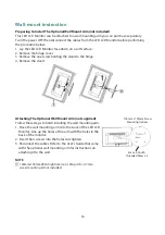
Page 18: ...ge 4 Remove the stand Attaching The Optional Wall Mount Arm not supplied Follow these steps to finish installing the wall mounting arm 1 Place the wall mounting arm onto the back of the LED LCD Monito...

Page 19: ...hez imm diatement le cordon d alimentation et appelez votre centre de service Never remove the rear cover of your LED LCD Monitor cabinet The display unit inside contains high voltage parts and may ca...

Page 20: ...http www planar com support for operations manuals touchscreen drivers warranty information and access to Planar s Technical Library for online trouble shooting To speak with Planar Customer Support...

Page 21: ...of their respective owners Technical information in this document is subject to change without notice Customer Service 24x7 Online Technical Support http www planar com support 1195 NE Compton Drive...

Reviews: