background image


13

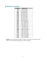
Supporting Timing Modes   

STANDARD 

RESOLUTION 

VGA 

720 x 400 @ 70Hz 

VGA 

640 x 480 @ 60Hz 

MAC 

640 x 480 @ 67Hz 

VESA 

640 x 480 @ 72Hz 

VESA 

640 x 480 @ 75Hz 

VESA 

800 x 600 @ 56Hz 

VESA 

800 x 600 @ 60Hz 

VESA 

800 x 600 @ 72Hz 

VESA 

800 x 600 @ 75Hz 

MAC 

832 x 624 @ 75Hz 

VESA 

1024 x 768 @ 60Hz 

VESA 

1024 x 768 @ 70Hz 

VESA 

1024 x 768 @ 75Hz 

VESA 

1280 x 960 @ 60Hz 

VESA 

1152 x 864 @ 75Hz 

MAC 

1152 x 870 @ 75Hz 

VESA 

1280 x 1024 @ 60Hz 

VESA 

1280 x 1024 @ 75Hz 

VESA 

1440 x 900 @ 60Hz 

VESA 

1440 x 900 @ 75Hz 

CVT 

1400 x 1050 @ 60Hz 

VESA 

1600 x 1200 @ 60Hz 

VESA 

1680 x 1050 @ 60Hz 

VESA 

1920 x 1080 @ 60Hz 

 
Warning: 

Do not set the graphic card in your computer to exceed these maximum refresh rates. 

Doing so may result in permanent damage to your LED LCD Monitor. 

Summary of Contents for PLL2710W

Page 1: ...www planar com USER S GUIDE LED LCD Monitor PLL2710W...

Page 2: ...First Setup 4 Front View of the Product 5 Rear View of the Product 6 Quick Installation 7 Advanced Operation OSD Menu 10 Supporting Timing Modes 13 Technical Information 14 Wall Mount Installation Ins...

Page 3: ...over users are encouraged to reduce interference by doing one or more of the following Reorient or relocate the receiving antenna Move the LED LCD Monitor and the receiver further away from each other...

Page 4: ...se abrasive cleaners waxes or solvents for your cleaning Do not operate the product under the following conditions o Extremely hot cold or humid environment o Areas susceptible to excessive dust and d...

Page 5: ...verview Congratulations on your purchase of this high performance edge lit LED LCD monitor This LED LCD Monitor comes with the following accessories LED LCD Monitor Base Power Cord VGA Signal Cable Us...

Page 6: ...e monitor the other hand attach the base to the stand 3 Stand the LED LCD Monitor up Disconnecting the stand base 1 Lay the LED LCD Monitor flat on a table with the LED screen face down To prevent the...

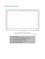
Page 7: ...5 Front View of the Product OSD Turn On Off Contrast Brightness Scroll Down Adjust Decrease Preset Mode Scroll Up Adjust Increase Confirm Select Input select Auto adjust Power ON OFF LED Indicator...

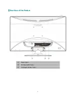
Page 8: ...6 Rear View of the Product Power Input DVI Input DVI 24 pin VGA Input D Sub 15 pin...

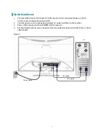
Page 9: ...nitor and computer are powered OFF 2 Connect power cord to a properly grounded AC outlet and then to the monitor 3 Power ON computer and then POWER ON the monitor 4 Set the timing mode on your compute...

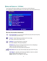
Page 10: ...r Auto mode Press the button for three seconds to auto adjust the image VGA only Select the desired item when in OSD menu When not in OSD menu directly enters Contrast Brightness Setting menu Select t...

Page 11: ...the POWER button are locked Press and hold the 1 button and the button for 3 seconds to lock all 5 buttons The LED LCD Monitor will show a Locking Power Button message for 5 10 seconds and the message...

Page 12: ...eground white level of screen image increase contrast decrease contrast Brightness To adjust the luminance of the video increase brightness decrease brightness ECO Mode Allows the user to change the E...

Page 13: ...Position move screen to the right move screen to the left V Position move screen up move screen down Fine Tune To adjust the delay time of data and clock Press or to adjust to your preference Sharpne...

Page 14: ...move OSD to the left V Position To vertically adjust the OSD position move OSD up move OSD down OSD Time Out To automatically turn off On Screen Display OSD after a preset period of time OSD Backgrou...

Page 15: ...1024 x 768 60Hz VESA 1024 x 768 70Hz VESA 1024 x 768 75Hz VESA 1280 x 960 60Hz VESA 1152 x 864 75Hz MAC 1152 x 870 75Hz VESA 1280 x 1024 60Hz VESA 1280 x 1024 75Hz VESA 1440 x 900 60Hz VESA 1440 x 900...

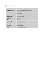
Page 16: ...Mode 0 5 Watt Off 0 5 Watt Displayable Resolution Full HD 1920 x 1080 max Vertical Frequency 60Hz max Pixel Dimension 0 3114 x 0 3114 mm Display Color 16 7M Tilt 0 20 Active Display Area 597 89 mm x...

Page 17: ...emove the stand Attaching The Optional Wall Mount Arm not supplied Follow these steps to finish installing the wall mounting arm 1 Place the wall mounting arm onto the back of the LED LCD Monitor Line...

Page 18: ...ains high voltage parts and may cause electric shock to human bodies Never try to repair your LED LCD monitor yourself Always call your service center or a qualified technician to fix it Troubleshooti...

Page 19: ...2013 P N 2001171358T...

Reviews: