2.2 Basic Component Description
A. The principle components of the aircraft alternators described herein are the slip ring end housing assembly
with bearing, the rectifier assembly, the stator, the rotor, the drive end housing assembly with bearing and the
brush holder assembly with spring and brushes.
B.
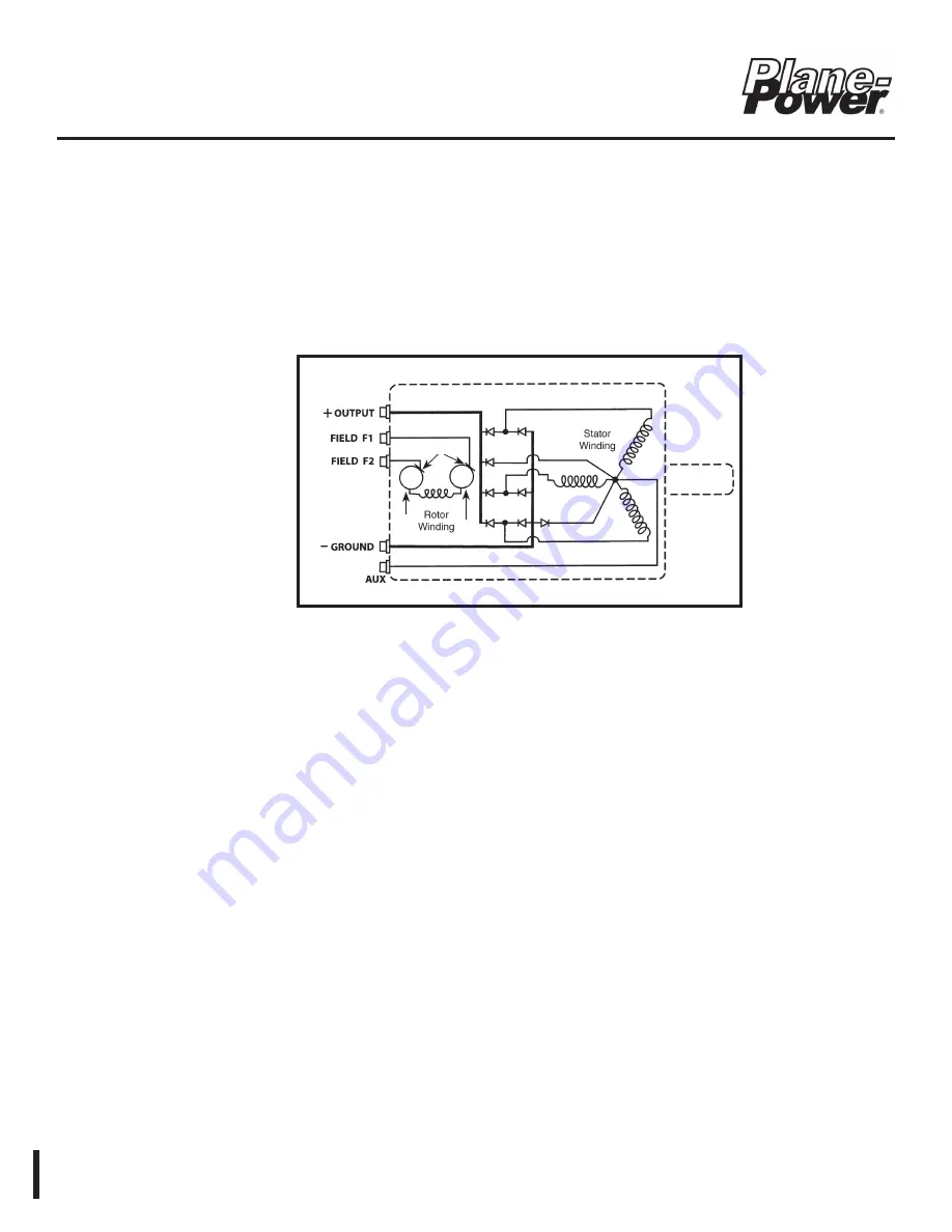
A simplified electrical diagram is shown in Figure 2.21 which shows the basic electrical operating points and
connections.
2.3 Technical Purpose
A. The purpose of the alternator is to produce electrical energy. This energy is used to maintain the proper state
of charge in the battery and supply current to the electrically powered equipment and accessories in the
aircraft. It performs this function by converting mechanical energy derived from its rotating parts into electricity.
(1) The BATTERY is the source of electrical power whenever the BAT Master Switch is ON and is the
source of power for starting the aircraft. Once started, the ALTERNATOR becomes the electrical power
source whenever the engine is running and the ALT Switch is turned ON. (Control systems may vary
with the aircraft/rotorcraft.)
Figure 2.21 - Basic Diagram
Rectifier Ass’y
Brushes
Slip
Ring
Slip
Ring
Aircraft Alternator
Maintenance Manual
ES1031
24-30-01
Rev. B: 20 Apr. 2022
Page: 2-15
© 2022 - Hartzell Engine Technologies - All rights reserved


