.
.
User’s manual
67
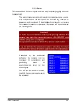
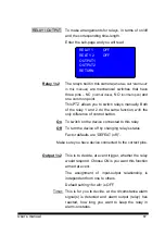
RELAY / OUTPUT To make arrangements for relays, in terms of on/off
and the corresponding time-length.
Enter the sub-page and you will read
Relay 1
&
2
The relays built in this camera
(what we call “alarm-out”
in this manual)
are mechanical switches that have
three pins – NC
(normal close)
, NO
(normal open)
and
one common point.
This PTZ allows you to switch relays manually. Both
of the relay 1 and 2 do the same function, with the
only difference of control button.
On
To switch on the device connected to this relay
Off
To turn the device off by changing relay’s status
Factor defaults are “DEFEAT (off)”.
Make sure you have device connected to the correct pins.
Output 1
&
2
This is to decide, at event trigger, whether the relay
would respond. Choose ON is you want this function
armed at event.
The assignment of input-output relationship is
independent from one to others.
Default setting <for all> is OFF.
Timer: This is for you to decide, at the circumstance alarm
signal(s) is detected and alarm output (relay) has
reacted, how long you want to keep the relay in
alarm-on status.
RELAY 1
OFF
RELEY 2
OFF
OUTPUT1
OUTPUT2
RETURN
Summary of Contents for CAM-ISD52
Page 1: ...23x Indoor Speed Dome Camera CAM ISD52 User s Manual ...
Page 2: ......
Page 49: ... User s manual 48 ...


