Introduction
3
There are three settings for the Power and LAN ( /WLAN ) LED to control the light
illumination for monitoring purpose from Normal / Off / Dummy.
Please refer to the
Web Configuration section for detailed information and usage.
Rear Panel
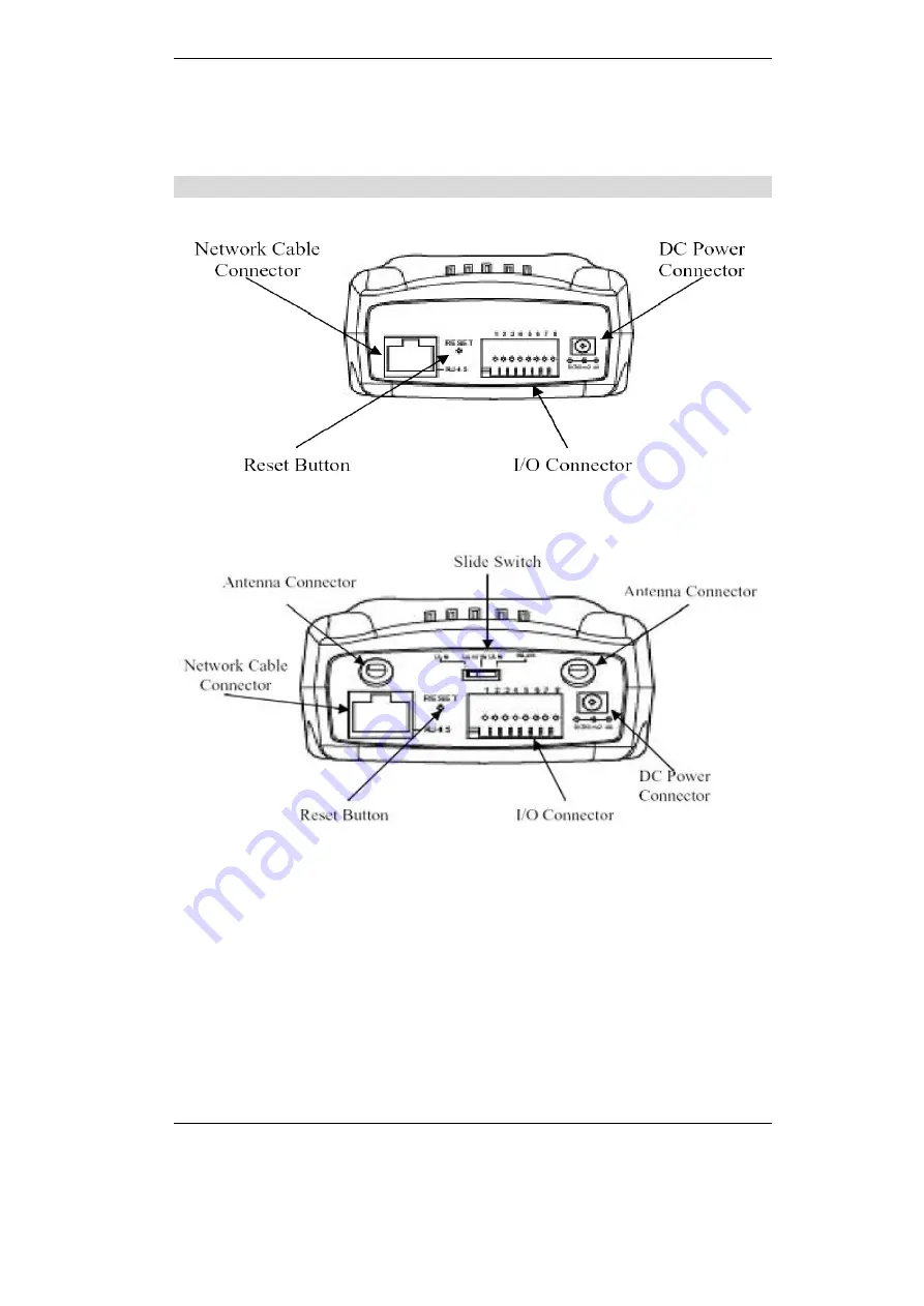
Figure 1-2: Rear panel of ICA-100
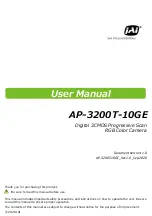
Figure 1-3: Rear panel of ICA-100W
Network Cable Connector
Internet Camera provides an RJ-45 connector for connections to 10Base-T Ethernet
cabling or 100Base-TX Fast Ethernet cabling (which should be Category 5 twisted-pair
cable). The port supports the NWay protocol, allowing ICA-100 series to automatically
detect or negotiate the transmission speed of the network.
DC Power Connector
The DC power input connector is located on ICA-100 series
’
s rear panel and is labeled
DC 5V with a single jack socket to supply power to ICA-100 series. Power will be
generated when the power supply is connected to a wall outlet.
Reset Button
Reset will be initiated when the reset button is pressed once and Power LED begins to
flash.
Factory Reset of ICA-100: Press the reset button for three seconds or until Power LED
Summary of Contents for ICA-100
Page 1: ...Internet Camera ICA 100 ICA 100W User s Manual ...
Page 13: ...Broadband Router User Guide 10 ...
Page 55: ...Broadband Router User Guide 52 Figure 5 26 Tools Screen ...
Page 58: ...Advanced Configuration 55 Figure 5 29 Motion Setting Screen ...
Page 61: ...Broadband Router User Guide 58 Figure 5 31 Case Sensitive Menu in Camera View Format ...


