7
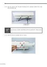
2.3.2 Use the wrench from the wall mounting kit to counterclockwise release the
screw and protective cap.
LAN cable in
I/O, Audio cable
out (Optional)
Counterclockwise
release screw
Counterclockwise
release protective cap
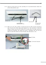
2.3.3 Slide an RJ-45 cable without its plug through the stand and the protective
cap. Then fix the RJ-45 plug and connect it to the connector of the PoE
module. Please note that the whole RJ-45 cable (with the plug) cannot go
through the protective cap. When the setup is completed, user can use PoE
tester to test PoE module to check whether the LED works or not.
PoE Module
Protective Cap
Stand
From 802.3at PoE Switch


