background image

22

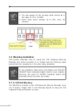
Note

1. The wire gauge for the terminal block should be in 

the range of 12 to 24 AWG.

2. Alarm relay circuit accepts up to 30V, max. 3A 

currents.

3.6  Mounting Installation

This section describes how to install the PoE Industrial Ethernet 
Extender and make connection to it. Please read the following topics 
and perform the procedures in the order being presented.

Note

In the installation steps below, this Manual uses IGS-801 
(PLANET 8-port Industrial Gigabit Switch) as an example. 
However, the steps for PLANET Industrial Switch and 
Industrial Media Converter are similar.


z

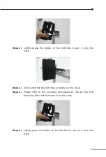
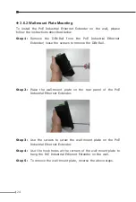
3.6.1 DIN-Rail Mounting

The DIN-Rail is screwed on the PoE Industrial Ethernet Extender when 

out  of  factory.  Please  refer  to  the  following  figures  to  hang  the  PoE 

Industrial Ethernet Extender on track.

Summary of Contents for IVC-2004PT

Page 1: ...PoE Industrial Ethernet Extender IVC 2004PT User s Manual ...

Page 2: ...quality performance merchantability or fitness for a particular purpose PLANET has made every effort to ensure that this User s Manual is accurate PLANET disclaims liability for any inaccuracies or omissions that may have occurred Information in this User s Manual is subject to change without notice and does not represent a commitment on the part of PLANET PLANET assumes no responsibility for any ...

Page 3: ...rence in which case the user will be required to correct the interference at his own expense CE Mark Warning This is a Class A product In a domestic environment this product may cause radio interference in which case the user may be required to take adequate measures WEEE Warning To avoid the potential effects on the environment and human health as a result of the presence of hazardous substances ...

Page 4: ...PT 12 2 1 2 DIP Switch Indication 13 2 2 The Upper Panel 14 3 Installation 15 3 1 Installing PoE Industrial Ethernet Extender IVC 2004PT 15 3 2 IVC 2004PT BNC RJ 11 Proper Connection 16 3 3 IVC 2004PT Application Connection 17 3 4 Wiring the Power Inputs 20 3 5 Wiring the Fault Alarm Contact 21 3 6 Mounting Installation 22 3 6 1 DIN Rail Mounting 22 3 6 2 Wall Mount Plate Mounting 24 4 Troubleshoo...

Page 5: ...ible data transmission speeds over the existing copper telephone lines or coaxial cables without the need for rewiring The IVC 2004PT PoE Industrial Ethernet Extender has a switching architecture with 4 PoE of RJ 45 10 100Mbps ports and Asymmetric or Symmetric Ethernet over VDSL port Asymmetric means upstream and downstream rate are not the same and Symmetric means upstream and downstream rate are...

Page 6: ...rnet Extender provides a lower cost replacement and smooth migration for the existing Long Reach Ethernet LRE networks The cable specifications of the connection are listed as follows z z 10Base T Category 3 4 or 5 UTP z z 100Base TX Category 5 5e or 6 UTP z z Ethernet over VDSL2 Twisted pair Telephone Wires z z Ethernet over VDSL2 Coaxial Cable Note Slave device CPE must be connected to Master de...

Page 7: ...n z z IP30 aluminum metal case protection z z Defines Asymmetric Band Plan 998 and Symmetric band plans for the transmission of Upstream and Downstream signals z z Complies with IEEE 802 3 IEEE 802 3u and IEEE 802 3x standards z z DMT Discrete Multi Tone line coding z z Half duplex back pressure and IEEE 802 3x full duplex fause frame flow control z z Supports up to 1536 bytes packet size 802 1Q V...

Page 8: ...table BNC and RJ 11 mode Selectable target Band Plan Selectable target SNR mode Encoding VDSL DMT ITU T G 997 1 ITU T G 993 1 VDSL ITU T G 993 2 VDSL2 Profile 17a Support LED Indicators P1 Green P2 Green Fault Green Master Green and Slave Green ACT Green Sync Green PoE Orange Power Over Ethernet PoE Standard IEEE 802 3af Power over Ethernet PSE PoE Type End Span PoE Power Input 24V or 48V DC power...

Page 9: ...53 18Mbps 1000m 38 8Mbps 1200m 33 5Mbps 1400m 28 2Mbps 200m 99 65Mbps 400m 99 64Mbps 600m 97 59Mbps 800m 94 51Mbps 1000m 84 45Mbps 1200m 73 37Mbps 1400m 61 28Mbps 1600m 54 20Mbps 1800m 48 13Mbps 2000m 39 9Mbps 2200m 35 6Mbps 2400m 31 4Mbps Symmetric Mode VDSL RJ 11 BNC 200m 91 99Mbps 400m 74 79Mbps 600m 54 51Mbps 800m 38 34Mbps 1000m 27 21Mbps 1200m 24 15Mbps 1400m 21 10Mbps 200m 95 99Mbps 400m 92...

Page 10: ...perature 40 75ºC Storage Temperature 40 85ºC Operating Humidity 10 to 90 relative humidity non condensing Storage Humidity 10 to 90 relative humidity non condensing Regulation Compliance FCC Part 15 Class A CE Standards Compliance IEEE 802 3 10Base T IEEE 802 3u 100Base TX IEEE 802 3af Power over Ethernet IEEE 802 3x Full duplex pause frame flow control ITU T 1 G 997 1 2 G 993 1 VDSL 3 G 993 2 VDS...

Page 11: ...al Ethernet Extender familiarize yourself with its display indicators and ports Front panel illustrations in this chapter display the unit LED indicators Before connecting any network device to the PoE Industrial Ethernet Extender read this chapter carefully 2 1 Front Panel The unit s front panel provides a simple interface monitoring the PoE Industrial Ethernet Extender z z IVC 2004PT Front Panel...

Page 12: ... over that port Sync Green Light Indicates that the VDSL link is established Fast Blink Indicates that the VDSL link is at training status about 10 seconds Slow Blink Indicates that the VDSL link is at idle status Master Green Light Indicates the VDSL Bridge is running at Master mode Slave Green Light Indicates the VDSL Bridge is running at Slave mode z z 10 100Base TX with PoE Port LED Color Func...

Page 13: ...ve BNC Asymm 6dB z z Master Salve t Master Central Office In the Master device mode usually the Master device will be located at the data center of ISP or enter prise to link to the backbone t Slave Customer Premises Equipment In the Slave device mode usually the Slave device will be located at branch office home or remote side as the long reach data receiver The Slave also can be connected to the...

Page 14: ...y default setting DIP 4 switch is set at ON position and operate as Slave To operate as Master please set DIP 1 switch to OFF position Adjust other DIP switch settings according to different network application demands Please power off the PoE Industrial Ethernet Extender before making any transmission mode adjustment 2 2 The Upper Panel The upper panel of the PoE Industrial Ethernet Extender cons...

Page 15: ...2004PT The device is used for Point to Point connection only Master device to Slave device and has equipped with one RJ 11 and one BNC connector for VDSL2 network connection Telephone Wire Depending on the quality of telephone line the maximum distance of RJ 11 segment is 1 4km 4593ft with AWG 24 telephone wires Coaxial Depending on the quality of coaxial cable the maximum distance of BNC segment ...

Page 16: ...axial Cable Connections 2 4km Max DIP 2 must switch to the BNC mode DIP 2 must switch to the RJ 11 mode No Connection Slave IVC 2002 P1 P2 Slave Master Sync ACT FAULT RJ 11 BNC VDSL 4 3 2 1 IVC 2004PT Master RJ 11 Symm 9dB Slave OFF ON BNC Asymm 6dB PoE In Use LNK ACT LNK ACT PoE In Use 1 2 3 4 ON 1 2 3 4 ON PoE Master IVC 2004PT PoE IP camera Ethernet Switch RJ 45 Connections 100m 328ft Max RJ 45...

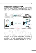
Page 17: ...2 4km RJ 11 1 4km PoE PoE PoE PoE VDSL2 VDSL2 PoE 100Base TX UTP with PoE 100Base TX UTP Figure 3 2 IVC 2004PT BNC and RJ 11 Connection With 4 PoE in line power interfaces the PoE Industrial Ethernet Extender can build a power central controlled IP phone system IP camera system and AP group for the enterprise For instance 4 cameras APs can be easily installed around the corner in the company for s...

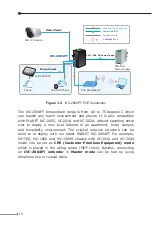
Page 18: ...ironment and places It is also compatible with PLANET IVC 2002 VC 201A and VC 202A without spending extra cost to deploy a new local Internet in an apartment hotel campus and hospitality environment The original network structure can be used to re deploy with our latest PLANET IVC 2004PT For example MC 700 MC 1500 and MC 1500R chassis with VC 201A and VC 202A inside can be set as CPE Customer Prem...

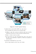
Page 19: ... PoE PoE PoE PoE Figure 3 4 IVC 2004PT Application Topology To decide where to put the IVC 2004PT you must ensure t It is accessible and cables can be connected easily t Cabling is away from sources of electrical noise such as radios transmitters and power lines and fluorescent lighting fixtures t Water or moisture must be avoided t Air Flow around the unit and through the vents in the side of the...

Page 20: ...is used for two DC redundant power inputs Please follow the steps below to insert the power wire 1 Insert positive negative DC power wires into contacts 1 and 2 for POWER 1 or 5 and 6 for POWER 2 Input DC 24V 48V V1 V1 V2 V2 PWR1 PWR2 Fault V1 V1 V2 V2 Note Must input 24V or 48V DC power source to make PoE function workable ...

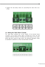
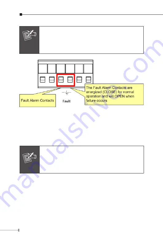
Page 21: ...contacts are in the middle of the terminal block connector as the picture shows below Inserting the wires the PoE Industrial Ethernet Extender will detect the fault status of the power failure and then forms an open circuit The following illustration shows an application example for wiring the fault alarm contacts Insert the wires into the fault alarm contacts ...

Page 22: ...he following topics and perform the procedures in the order being presented Note In the installation steps below this Manual uses IGS 801 PLANET 8 port Industrial Gigabit Switch as an example However the steps for PLANET Industrial Switch and Industrial Media Converter are similar z z 3 6 1 DIN Rail Mounting The DIN Rail is screwed on the PoE Industrial Ethernet Extender when out of factory Please...

Page 23: ...t onto the track Step 2 Check whether the DIN Rail is tightly on the track Step 3 Please refer to the following procedures to remove the PoE Industrial Ethernet Extender from the track 2 1 Step 4 Lightly press the button of the DIN Rail to remove it from the track ...

Page 24: ...nder loose the screws to remove the DIN Rail Step 2 Place the wall mount plate on the rear panel of the PoE Industrial Ethernet Extender Step 3 Use the screws to screw the wall mount plate on the PoE Industrial Ethernet Extender Step 4 Use the hook holes at the corners of the wall mount plate to hang the PoE Industrial Ethernet Extender on the wall Step 5 To remove the wall mount plate reverse the...

Page 25: ...sing the Cat 5 5e or 6 cables with RJ 45 connector to connect to the port 2 If your device like LAN card supports Auto Negotiation please try to modify at a fixed speed of your device manually 3 Check whether the extender s and the connected device s power are ON 4 Check whether the cables are firmly seated in its connectors in the switch and in the associated device 5 Check whether the connecting...

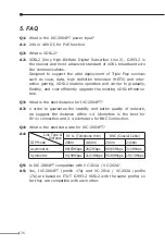
Page 26: ...infrastruc ture Q3 What is the best distance for IVC 2004PT A3 n order to guarantee the stability and better quality of network we suggest the distance within 1 4 kilometers is the best for RJ 11 connection and 2 4 kilometers for BNC Connection Q4 What is the best data rate for IVC 2004PT A4 Link Type Distance DIP Mode RJ 11 Telephone Wire BNC Coaxial Cable 200m 1400m 200m 2400m Asymmetric 99 63Mb...

Page 27: ...annel over a network channel The greater the ratio the easier it is to identify and subsequently isolate and eliminate the source of noise Generally speaking the higher SNR value gets the better the line quality but lower performance Q7 What is band plan and what s the effect A7 VDSL2 defines multiple band plans and configuration modes profiles to allow asymmetric and symmetric services in the sam...

Page 28: ...006 A1 2007 EN 61000 3 2 2006 A2 2009 EN 61000 3 3 2008 EN 55024 1998 A1 2001 A2 2003 IEC 61000 4 2 2008 IEC 61000 4 3 2008 IEC 61000 4 4 2004 IEC 61000 4 5 2005 IEC 61000 4 6 2008 IEC 61000 4 8 2009 IEC 61000 4 11 2004 Responsible for marking this declaration if the Manufacturer Authorized representative established within the EU Authorized representative established within the EU if applicable C...

Reviews: