background image


Step 3 - Check the height of the M3 (diagonal) mirror 


This alignment is performed at the factory and normally should not need to be adjusted. If you 
determine that some adjustment is necessary after working through the steps below, contact 
PlaneWave Instruments for details. 

If you wish to verify the height of the M3 mirror: 

A.


Remove the bottom dovetail, side panel, and primary baffle tube as described in the 
Secondary Mirror alignment procedure 

B.


Install the aligned laser adapter in either the Port 1 or Port 2 side of the telescope, and 
turn on the laser 

C.


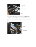
Rotate the M3 mechanism by hand (back-driving the motor) until the mirror is halfway 
between the Port 1 and Port 2 positions. When the mirror is at just the right angle, the 
laser beam should slightly graze across the surface of the mirror.  

Step 4 - Adjust the M3 (diagonal) mirror relative to Port 1 


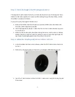
1.


In the PlaneWave Interface control software, select the "M3" tab and move the mirror 
to Port 1. 

2.


Remove any imaging equipment from Port 1, including the IRF90 Rotating Focuser. 


3.


Insert the 2" Laser Adapter and laser into Port 1, and secure it using the locking ring and 
three screws. 
 

Summary of Contents for CDK700

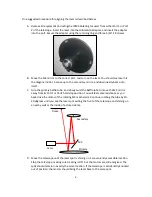
Page 1: ...700 telescopes typically ship with a laser that can be inserted into a 1 25 or 2 diameter eyepiece tube This tube is attached to a plate that can be secured to the two Nasmyth ports on the side of the telescope and to a port on the backplate of the telescope To produce the most accurate collimation and to simplify later steps of the collimation process the laser must be aligned to be perpendicular...

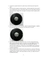
Page 2: ...ube and slowly twist the baffle tube to move the M3 mirror away from its Port1 or Port2 hardstop position You will feel some resistance as you back drive the motor of the rotating M3 mechanism Continue rotating the tube by 10 20 degrees until you see the laser spot exiting the front of the telescope and shining on a nearby wall or the inside of a closed dome D Move the telescope until the laser sp...

Page 3: ... H Adjust the knobs that hold the laser in the 1 25 or 2 tube and try to get the laser beam positioned halfway between the two marks on the paper Note Unfortunately these adjustments are fairly imprecise However you should be able to get the alignment close through various combinations of loosening tightening each knob and spinning the laser inside the tube Future revisions of the laser tool will ...

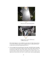
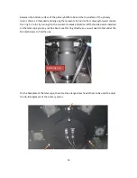
Page 4: ... wires that control the M3 mirror Unplug or unscrew detach each of these wires including a M3 motor control DB9 secured with screws b Port 1 limit switch 2 pin molex c Port 2 limit switch 2 pin molex d M3 temperature sensor 3 pin molex e M3 dew heater 2 pin molex Shine a flashlight inside and note the position of the 3 screws that hold the M3 mechanism into place These screws will be removed in a ...

Page 5: ...tions each held in place with six screws These sections can be removed one at a time but you may find it easier to remove the entire tube as a single unit It can be helpful to have two people lifting the tube in this case Unscrew the bottom edge of the tube from the M3 rotating mechanism Lift the tube straight up until it clears the diagonal M3 mirror Tilt the tube slowly and guide it out between ...

Page 6: ... no preferred optical axis Centering adjustments can be made by loosening tightening opposing pairs of spider vanes using the tension screws on the upper truss blocks Tip tilt adjustments can be made using the three push screws and the central pull screw knob behind the secondary mirror P If the alignment of the laser is in question rotate the laser adapter 180 degrees as you did when first aligni...

Page 7: ...d laser adapter in either the Port 1 or Port 2 side of the telescope and turn on the laser C Rotate the M3 mechanism by hand back driving the motor until the mirror is halfway between the Port 1 and Port 2 positions When the mirror is at just the right angle the laser beam should slightly graze across the surface of the mirror Step 4 Adjust the M3 diagonal mirror relative to Port 1 1 In the PlaneW...

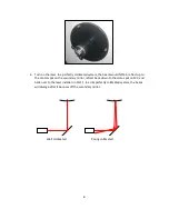
Page 8: ...3 reflect up to the center spot on the secondary mirror reflect back down to the same spot on M3 and back over to the laser installed in Port 1 In an imperfectly collimated system the beam will diverge after it bounces off the secondary mirror Well collimated Poorly collimated ...

Page 9: ...ould trace out a circle If this is the case the ideal alignment is against the center of that circle There are two M3 adjustments for each port The rotation adjustment is performed by loosening a set screw and loosening tightening the hardstop screw that the hardstop block runs against A magnet should pull the hardstop block firmly against the screw Poor alignment Need to tilt the mirror down Bett...

Page 10: ...ets either repel each other tilting the mirror up for one port or attract each other tilting the mirror down for the other port If you are uncertain which hardstop screwis used for which port try tilting the mirror up or down release it and check to see which screw the hardstop pin hits Hardstop block Hardstop screw Set screw Jam nut Alignment screw ...

Page 11: ...heck that the laser or perhaps the center of the circular path traced by spinning the laser adapter aligns with the spot that has been marked at the center of the secondary Because the secondary mirror is spherical and has no preferred optical axis this alignment is not critical However if the alignment is off by more than 1 4 inch or so you may start to introduce some vignetting Each port can be ...

Page 12: ... forget to plug in the side panel fans Step 6 Align the Primary Mirror At night slew to a fairly bright star and take the star out of focus If the telescope is well collimated the defocused star should appear concentric with light being evenly distributed around the disc that is formed If the telescope is poorly collimated one portion of the disc will appear thinner in size and brighter in intensi...

Page 13: ...en this ring 1 2 turns by turning it in the counter clockwise direction With the side panels installed on the telescope you may not be able to see this ring directly so you will need to feel under the M3 mechanism to find the ring On the backplate of the telescope there are three large screw heads that can be used to adjust the tip tilt alignment of the primary mirror Retaining ring ...

Page 14: ... screws before adjusting the primary These should be re tightened once any adjustments have been completed The goal is to tilt the mirror so that the star moves in the same direction as the thick portion of the out of focus disc Eventually the starlight should be evenly distributed around the disc Locking screws Tip tilt screw Move star in this direction ...

Page 15: ... the light such as a book As you move your obstruction around the aperture of the telescope the location of this shadow will change By placing your arm at a position directly in front of each primary adjustment screw you can estimate the direction that the star will move when that screw is turned For example suppose you label the three adjustment screws A B and C If you place your arm in front of ...

Page 16: ... to switch to another screw to fine tune the collimation in some other direction Once the defocused star looks concentric tighten the 3 locking screws around each adjustment screw if available and verify that collimation did not change When you are finished reach under the M3 mechanism and tighten down the primary mirror retaining ring by spinning it clockwise until it is just slightly snug Direct...

Reviews: