background image

FORMA FIREPLACES


Copyright Planika Sp. z o.o.            

www.planikausa.com 

I1459#00 

  08.01.2020


FU

E

L


CLEARANCES  
AND INSTALLATION  
MANUAL 


Please read these instructions completely before  
installing or operating the Forma Fireplaces 


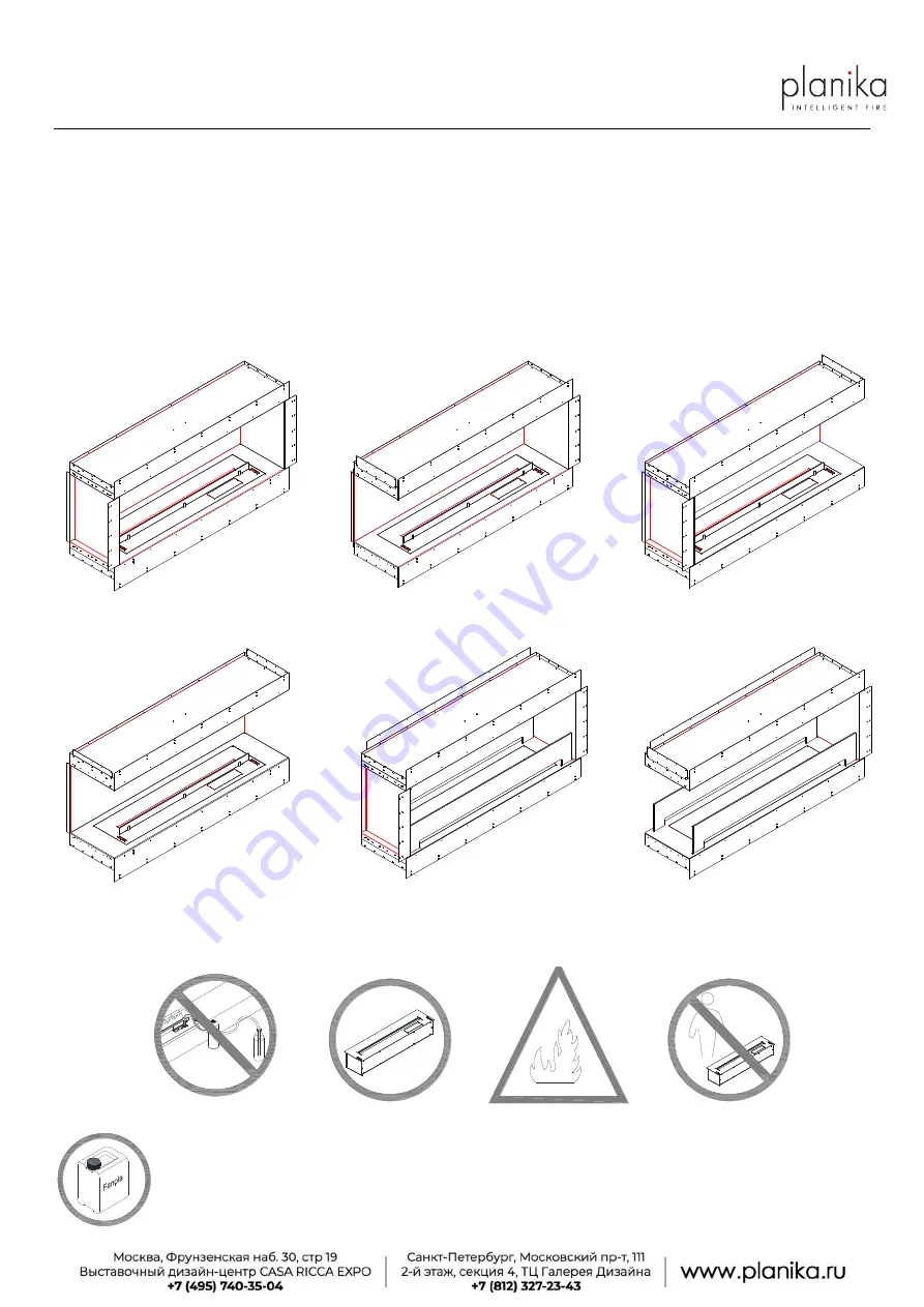
          Front                                                   Left Corner                                               Right Corner 


    Three-sided                                              Tunnel                                                    Room Divider 

Warnings: 

If the information in this manual is not followed exactly, a fire or explosion may result causing property damage, personal injury or loss of life. 


                    Do not fill while operating 

Use Planika burners only 

Flammable 

      Keep away from children 


FANOLA Bioethanol is the ONLY fuel to be used in this appliance.


Do not use gel, thick and viscous fuels or fuels of improper electric conductivity. The values must be compliant with those of FANOLA®. 

Other fuels, such as dehydrated ethanol (i.e. consisting of more than 96.6% by volume ethanol) will cause a device error and loss of the 
product warranty. Fuels consisting of 100% by volume ethanol will damage the device. Use only fuels consisting of 86-96.6% ethanol by 
volume. FANOLA Bioethanol fuel is the only recommended fuel.


Summary of Contents for FORMA 1200

Page 1: ...or loss of life Do not fill while operating Use Planika burners only Flammable Keep away from children FANOLA Bioethanol is the ONLY fuel to be used in this appliance Do not use gel thick and viscous fuels or fuels of improper electric conductivity The values must be compliant with those of FANOLA Other fuels such as dehydrated ethanol i e consisting of more than 96 6 by volume ethanol will cause ...

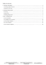
Page 2: ...nimum room sizes 4 2 APPLIANCE INSTALLATION 5 2 1 Framing 5 2 2 Definitions 5 2 3 Before getting started 5 3 BUILT IN INSTALLATION 7 3 1 Front Installation 7 3 2 Left Right Corner Installation 10 3 3 Three sided Installation 13 3 4 Tunnel Installation 16 3 5 Room Divider Installation 20 ...

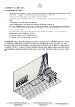
Page 3: ...stible materials see image below and Minimum Room Size table Room air exchange rate min 1 h Keep children animals and unauthorized persons at a safe distance at all times and never leave them unsupervised when the appliance is on or hot Do not use the device in humid and drafty spaces Do not cover top ventilation openings of the device WARNING Risk of Fire or Burns Provide adequate clearance aroun...

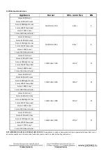
Page 4: ... Room Divider Forma 1800 Front FLA3 FLA3 1490 150 m3 15 Forma 1800 Left Corner Forma 1800 Right Corner Forma 1800 Three sided Forma 1800 Tunnel Forma 1800 Room Divider Forma 2300 Front FLA3 FLA3 1990 210 m3 21 Forma 2300 Left Corner Forma 2300 Right Corner Forma 2300 Three sided Forma 2300 Tunnel Forma 2300 Room Divider Forma 2700 Front FLA3 FLA3 2490 270 m3 27 Forma 2700 Left Corner Forma 2700 Ri...

Page 5: ...s been installed IMPORTANT The framing above the appliance must be self supporting The appliance is not load bearing IMPORTANT Minimum space from bottom 2 cm Burner cannot stand on floor or any other surface 2 2 Definitions Combustible materials Materials made of or surfaced with wood compressed paper plant fibers plastics or other material that can ignite and burn whether flame produced or not or...

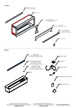
Page 6: ...eninsula and Double sided Installation manual Glass shield FLA3 FLA3 790 990 1190 1 piece FLA3 FLA3 1490 1990 2490 2 pieces Glass shield connector FLA3 FLA3 790 2 pieces FLA3 FLA3 990 1190 3 pieces FLA3 FLA3 1490 1990 2490 4 pieces Small glass holder FLA3 FLA3 790 2 pieces FLA3 FLA3 990 1190 3 pieces FLA3 FLA3 1490 1990 2490 4 pieces Burner Remote control Fuel pump Service cable Installation and u...

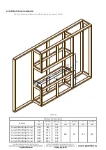
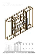
Page 7: ... in Table A Table A Framework opening size Appliance W W1 min W2 max D D1 max H H1 min mm mm mm mm mm mm mm Forma 1000 Front 1120 820 150 450 50 710 240 Forma 1200 Front 1320 1020 150 Forma 1500 Front 1630 1230 200 Forma 1800 Front 1930 1530 200 Forma 2300 Front 2440 2040 200 Forma 2700 Front 2800 2500 150 H H1 ...

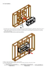
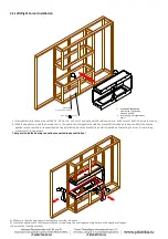
Page 8: ...e square while in transport and during installation Keep the bracket s on while framing up the setting to assist in minimizing movement of the appliance The space inside the housing cannot be connected to any ventilation a Make sure that the appliance is level before securing it in place b Secure the appliance to the framework with screws using the existing mounting holes on the appliance flanges ...

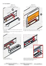
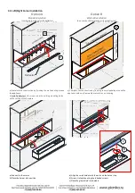
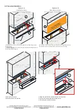
Page 9: ... b Install deflector with screws using the existing mounting holes on ceiling of the fireplace a Complete the construction by finishing the wall paneling around the appliance with non flammable materials as on drawing a Connect to the mains b Place the burner into position a Align the small holder with the holes on the burner top b Screw it into place using the included screws c Place the glass sh...

Page 10: ...s Appliance W W1 min W2 max D D1 max H H1 min mm mm mm mm mm mm mm Forma 1000 Left Right Corner 1120 820 150 450 50 710 240 Forma 1200 Left Right Corner 1320 1020 150 Forma 1500 Left Right Corner 1630 1230 200 Forma 1800 Left Right Corner 1930 1530 200 Forma 2300 Left Right Corner 2440 2040 200 Forma 2700 Left Right Corner 2800 2500 150 H H1 ...

Page 11: ...tallation Keep the bracket s on while framing up the setting to assist in minimizing movement of the appliance The space inside the housing cannot be connected to any ventilation a Make sure that the appliance is level before securing it in place b Secure the appliance to the framework with screws using the existing mounting holes on the appliance flanges c Remove the stability brackets Optional S...

Page 12: ...e appliance b Install deflector with screws using the existing mounting holes on the ceiling of the fireplace a Complete the construction by finishing the wall paneling around the appliance with non flammable materials as on drawing a Connect to the mains b Place the burner into position a Align the small holder with the holes on the burner top b Screw it into place using the included screws c Pla...

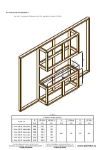
Page 13: ...amework opening sizes Appliance W W1 min W2 max D D1 max H H1 min mm mm mm mm mm mm mm Forma 1000 Three sided 1098 820 150 450 50 710 240 Forma 1200 Three sided 1301 1020 150 Forma 1500 Three sided 1606 1230 200 Forma 1800 Three sided 1911 1530 200 Forma 2300 Three sided 2419 2040 200 Forma 2700 Three sided 2774 2500 150 ...

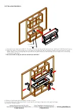
Page 14: ...nce square while in transport and during installation Keep the bracket s on while framing up the setting to assist in minimizing movement of the appliance The space inside the housing cannot be connected to any ventilation a Make sure that the appliance is level before securing it in place b Secure the appliance to the framework with screws using the existing mounting holes on the appliance flange...

Page 15: ...ppliance b Install deflector with screws using the existing mounting holes on the ceiling of the fireplace a Complete the construction by finishing the wall paneling around the appliance with non flammable materials as on drawing a Connect to the mains b Place the burner into position a Align the small holder with the holes on the burner top b Screw it into place using the included screws c Place ...

Page 16: ...le D Framework opening sizes Appliance W W1 min W2 max D D1 max H H1 min mm mm mm mm mm mm mm Forma 1000 Tunnel 1120 820 150 406 50 710 240 Forma 1200 Tunnel 1320 1020 150 Forma 1500 Tunnel 1630 1230 200 Forma 1800 Tunnel 1930 1530 200 Forma 2300 Tunnel 2440 2040 200 Forma 2700 Tunnel 2800 2500 150 H H1 ...

Page 17: ... up the setting to assist in minimizing movement of the appliance The space inside the housing cannot be connected to any ventilation a Make sure that the appliance is level before securing it in place b Align the flange extension panel with the threaded holes on the appliance Screw it into place using the included screws bottom row onto appliance top row onto framing material to secure it into po...

Page 18: ... wall paneling around the appliance b Install deflector with screws using the existing mounting holes on the ceiling of the fireplace a Complete the construction by finishing the wall paneling around the appliance with non flammable materials as on drawing on both sides a Connect to the mains b Place the burner into position Do not install the burner s glass shield included with the burner a b a b...

Page 19: ...3 4 Tunnel Installation 19 Install the windscreen by inserting the two ends into appropriate slots in the appliance Repeat the same for the back side windscreen ...

Page 20: ...opening sizes Appliance W W1 min W2 max D D1 max H H1 min mm mm mm mm mm mm mm Forma 1000 Room Divider 1120 820 150 406 50 710 240 Forma 1200 Room Divider 1320 1020 150 Forma 1500 Room Divider 1630 1230 200 Forma 1800 Room Divider 1930 1530 200 Forma 2300 Room Divider 2440 2040 200 Forma 2700 Room Divider 2800 2500 150 H H1 ...

Page 21: ...ming up the setting to assist in minimizing movement of the appliance The space inside the housing cannot be connected to any ventilation a Make sure that the appliance is level before securing it in place b Align the flange extension panel with the threaded holes on the appliance Screw it into place using the included screws bottom row onto appliance top row onto framing material to secure it int...

Page 22: ...l paneling around the appliance b Install deflectors along both sides with screws using the existing mounting holes on ceiling of the fireplace a Complete the construction by finishing the wall paneling around the appliance with non flammable materials as on drawing on both sides a Connect to the mains b Place the burner into position Do not install the burner s glass shield included with the burn...

Page 23: ...3 5 Room Divider Installation 23 Install the windscreen by inserting the two ends into appropriate slots in the appliance Repeat the same for the back side windscreen ...

Reviews: