Copyright Planika Sp. z o.o.
www.planikafires.com
IG0139#02
30.07.2018
27
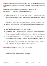
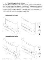
5.9.3.
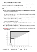
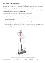
Construction of the concentric flue system
Correctly installed and configured concentric flue system by the Installer will ensure an optimized air
circulation inside the device and provide the best image of the flame.
In case of output of the concentric flue system through the side wall (type C11), the following requirements
apply:
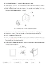
Install the system in accordance with the applicable regulations, taking into account all the difficulties
related to the wind pressure on the terminal.
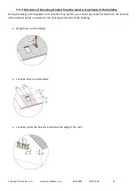
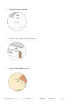
Drill holes of the correct diameter in the walls/ceilings through which concentric flue system will be
passing. The remaining space should be supplemented by additional protective insulation against the
ingress of moisture into the building.
If the concentric flue system is located near the combustible walls (elements) you must ensure a
minimum distance of 100 mm from flammable materials.
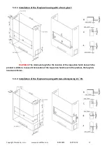
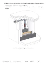
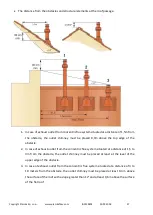
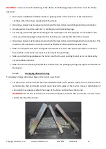
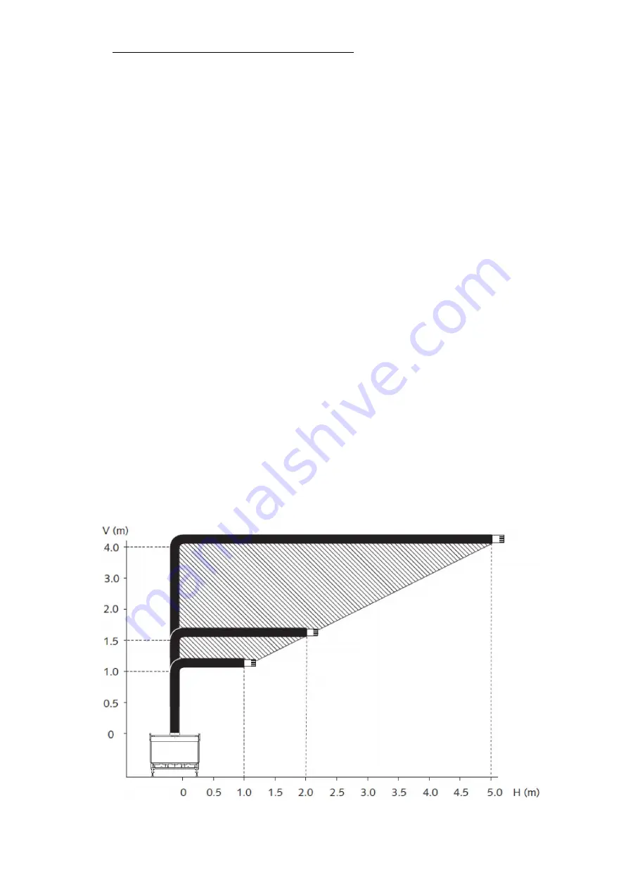
Installation of the concentric flue system should always start with the one meter vertical section
(minimum height) at the outlet of the device.
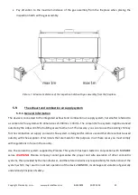
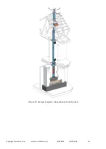
Total height of the pipe in vertical position, in case of concentric flue system getting through the wall
of the building, may not exceed a maximum length of 4 m.
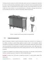
Total length of the pipe in horizontal position, in case of concentric flue system getting through the
wall of the building, may not exceed a maximum length of 5 m (not including terminal).
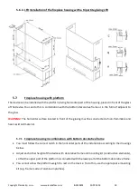
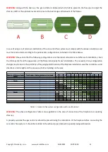
WARNING!
For the insert using LPG, it is recommended to use up to 2 meter of horizontal section (not
including terminal).
Picture 8 – Possible system configurations with the wall terminal