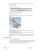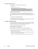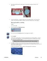
background image

14

Administration

Planmeca PlanScan User Manual

Instructions for High Level Disinfection Tips

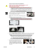
DO NOT use a chemical sterilant on tips with the autoclave symbol.  

DO NOT Autoclave tips without the autoclave symbol.  

DO NOT place in Ultrasonic Cleaner. 

Note: These instructions were validated using MaxiCide Plus w/ Activator (3.4% 

Gluteraldehyde) disinfectant available from Henry Schein Dental (#102-2865).

Clean the tip for 2 minutes under running tap water at 22 - 25°C (4 liters/minute) to remove 

debris.

Test the potency of your activated MaxiCide Plus prior to disinfection. (Recommend MetriTest 

Strips by Metrex (HSD  #602-3437)

Immerse the tip in activated MaxiCide Plus for 120 minutes (2 hours).

Note: Do not leave the tips soaking overnight.

Remove tip from the disinfectant.

Rinse disinfected part in three separate copious amounts of distilled water (1000 ml volume of 

water; minimum of 2” head height while part is immersed).

Agitate the tip in the water for 30 seconds and then let it stand in the water for another 30 

seconds.

Repeat the agitation and soak in each of the other two containers with fresh distilled water.

Storage

Wipe water off mirror using non-woven optical wipes (recommend Kimwipes Lens Cleaning 

#101-7070).

Optional: Insert tip into a sterilization pouch. (recommend Self Seal Sterilization Pouch 5 ¼” x 

10” [200/box] #112-4854)

Store for later use.

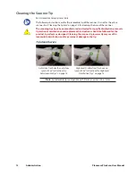
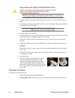
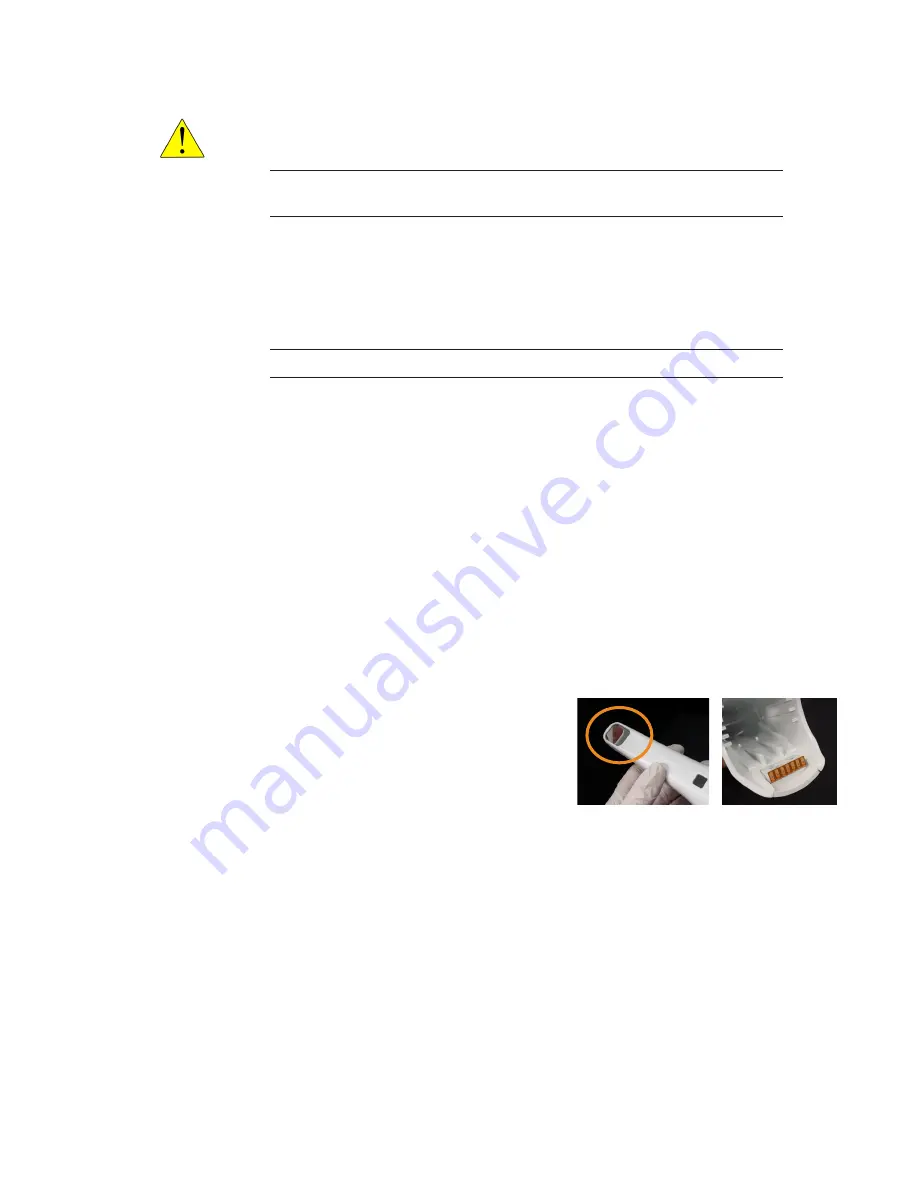
Prior to scanning, visually confirm the scanning 

mirror and scanner connection points of the 

scanning tip are clean and dry. To clean either 

surface, use an optical cloth or 2x2 gauze with a 

small amount of alcohol to gently remove residue. 

Ensure each surface is dry before connecting it to 

the scanner. 

Cleaning the System

For intraoral scanning systems only.

Protect the keyboard with a disposable barrier.

Cleaning Cycle: Before and after each use, clean all areas of the  Planmeca PlanScan System.

Summary of Contents for PlanScan

Page 1: ...Planmeca PlanScan User Manual ...

Page 2: ......

Page 3: ...reens 9 Version 9 Reset Warnings 9 Sprue Angle Method 10 Margin Ramp 10 Spacer Thickness 10 Dropper Tool 10 Spaceball Settings 10 Network Settings 10 Workbook Exercises 10 Mill Notification Settings 10 Milling Settings 10 Auto or Occlusal POI 10 Administration 11 Relocating the Laptop and or Scanner 11 System Information and Upgrades 11 Software and Hardware 11 Connecting the Scanning Tip 11 Disco...

Page 4: ...the First Scan 23 Scanning Overview 23 Scanning Live View 24 Scanning Options 25 Adjust Live View Window Size 25 Adjust the Scanning Field of View 26 Evaluating Your Model 26 Checking Your Model For Missing Data 26 Eraser Tool 27 Reset Model 27 Delete Model 27 Scanning Occlusion Data 28 Scanning a Bite Registration 28 Bite registration preparation 28 Bite registration scanning 29 Goals 29 Selectin...

Page 5: ...plicable Standards 47 Product Safety 47 EMC 47 Laser Product Safety 47 Packaging and Environmental 48 Biocampatibility 48 European Standards 48 Canadian Standards 48 US Food and Drug Administration 48 International Standards 48 Approvals All Systems 48 Guidance and Manufacturer s Declaration Electromagnetic Emissions 49 Guidance and Manufacturer s Declaration Electromagnetic Immunity 49 Recommende...

Page 6: ...The Planmeca Fit System requires Planmeca Romexis software revision 3 4 0 R or later Associated Documentation Planmeca Romexis User s Manual publication number 10014593 Note Throughout the documentation important notes and items of interest are formatted like this example Warning The orange Warning denotes something that can cause personal injury or physical damage to the equipment Some of the scr...

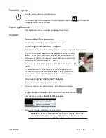
Page 7: ...the red FireWire connector of the scanner into the white Thunderbolt adapter The laptop gives an audible signal to confirm that the connection is fully seated To remove the scanner hold the red end with one hand and with the other hand grasp the Thunderbolt adapter Gently pull apart to disconnect Leave the white Thunderbolt adapter attached to the computer Disconnecting the Thunderbolt Adapter If ...

Page 8: ...Moving Viewing the 3D Model Use the mouse to zoom in or out move and rotate the composite model Using the Mouse Rotating the Model 1 Click and hold down the right mouse button 2 Drag the mouse horizontally vertically or diagonally to rotate the image Drag in small increments for more control 3 Release the mouse button to stop rotating Repeat as needed Changing the Model Size Use the scroll wheel o...

Page 9: ...reen for communicating with associates or Customer Support To take and save a screenshot ASUS Press Prt Sc keys simultaneously HP Press Fn Prt Sc keys simultaneously The computer takes a screenshot and saves it in Libraries Pictures Screenshots The screenshots are automatically numbered You can rename them if desired The Settings Screens Click the Settings button on the CAD CAM screen or the Setti...

Page 10: ...n systems Spaceball Settings Optional accessory Network Settings This screen should be used only under the supervision of a customer service representative These settings are pre configured and should not be changed Workbook Exercises For Classic systems Mill Notification Settings For Classic systems Milling Settings For mill systems Auto or Occlusal POI For mill systems ...

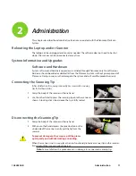
Page 11: ...anning Tip After disinfection if scanning intraorally See insert with scanning tips for further details 1 Grasp the body of the scanner with one hand 2 Use the other hand to press the scanning tip onto the scanner as shown A locking click is heard once the tip is fully seated Disconnecting the Scanning Tip 1 Grasp the body of the scanner with one hand 2 With your other hand depress the green butto...

Page 12: ... specific disinfection protocols Operational maintenance and replacement instructions should be followed for the product to perform as designed Cleaning the scanner tip incorrectly may result in incomplete disinfection and or permanent damage to the tip Tip Identification Autoclave Tips have the autoclave symbol See Instructions for Autoclaveable Tips on page 13 High Level Disinfection Tips have n...

Page 13: ...dividually pouch each scanner tip using an autoclave pouch ex HSD 112 4854 or a comparable product Note Autoclave baskets are not indicated for this cleaning procedure 3 Place one to three pouches per tray or cassette 4 Select the Wrapped Wrapped Instruments or Pouch cycle on the autoclave with a minimum cycle of 132 C 269 F with a sterilization time of 5 minutes After cycle completion store for l...

Page 14: ...s of distilled water 1000 ml volume of water minimum of 2 head height while part is immersed Agitate the tip in the water for 30 seconds and then let it stand in the water for another 30 seconds 6 Repeat the agitation and soak in each of the other two containers with fresh distilled water Storage 1 Wipe water off mirror using non woven optical wipes recommend Kimwipes Lens Cleaning 101 7070 2 Opti...

Page 15: ...rmicide to the entire surface of the scanner base scanner holder mouse mousepad and any other surfaces that you touch that were not covered by a disposable barrier Do not spray the germicide directly on the items and do not submerge the scanner or mouse in the germicide 2 Follow the germicide manufacturer s instructions Additional Assistance Go to http e4d com for videos and downloadable documenta...

Page 16: ...ducts must be installed and placed into service according to the EMC information provided in the documentation that accompanies the Planmeca products Portable and mobile RF Radio Frequency communications equipment can affect medical electrical equipment The wireless components in the Planmeca products may be interfered with by other equipment even if the other equipment is fully compliant with CIS...

Page 17: ...ton is used Note To view the newly created patient on the list perform new patient search Searching Patients Patients can be searched by ID or by name In Patient Management type any part of the patient s name or ID number into the Search field Matching items automatically appear as you type Note The system looks for the letters or numbers anywhere in the patient s name or ID Angela Angie and Dange...

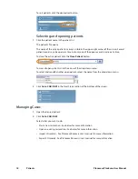
Page 18: ...t click the Close Patient button To view all open patients click the arrow of the drop down menu To select and modify another open patient select the name from the drop down menu 2 Click Go to CAD CAM in the Next Steps section at the bottom of the screen Managing Cases 1 Open the desired patient 2 Click Go to CAD CAM Select what you want to do Start a new restoration See below for more information...

Page 19: ...k New Scan Only if you do not have a design license 2 To open an existing scan or restoration crown inlay onlay etc double click a case on the list or click the Open Restoration button The case opens in the Planmeca PlanScan Setup tab Setup tab Use the Setup screen to set the restoration type occlusal data type material and tooth library If you open an existing restoration many of these settings m...

Page 20: ... scanner The scanner captures the restoration site with a laser system and delivers live images to the monitor As you capture images the system creates a composite model revealing any areas that need further scanning Ensure the power cord is being used on the laptop while scanning Scan Tab Layout 1 Scan Type 2 Scanner Indicators 3 Model Editing Tools 4 Evaluation Tools 5 Alignment Tools 1 3 4 5 2 ...

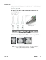
Page 21: ...g requires a Color Activation Kit sold separately Contact your local representative for upgrade details The live view shows the differences in the scanning tips The standard tip has a higher focal point and captures more data at once This can be a problem with active tongues Landscape has a horizontal field of view and portrait is vertical Standard Landscape Portrait Note Landscape and portrait ti...

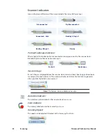
Page 22: ...e Session Usage Session Usage is displayed above the scanner status icon and shows how long you have been scanning on this particular case This number refreshes each time the Scan tab is opened or when you click the Refresh icon next to it Note This feature is only available on new tips Autoclave Indicator The autoclave symbol indicates that an autoclave tip is in use Color Indicator The color sym...

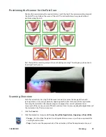
Page 23: ...ge of the tooth pre operative or wax up preparation opposing teeth buccal bite and or bite registration Scanning the restoration site requires proper site preparation correct placement and movement of the scanner and a sufficient number of scans to ensure adequate digitalization of the restoration site The basic steps are 1 Click the Scan tab 2 Click the desired scanning mode Pre op Prep Bite Regi...

Page 24: ... degree angle to the occlusal surface If the first scan is not optimal delete it and retake it 6 Continue taking scans until the composite model is fully formed 7 Click the button on the scanner to deactivate the laser 8 Evaluate the model Scan more if needed 9 Click Generate Model or press M on the keyboard to finish building the model 10 Make adjustments as needed 11 Select the next scan type 12...

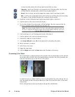
Page 25: ...ard to create the 3D model If you exit without generating the model the scans will be lost Click Data Density View to evaluate the model for low data See Checking Your Model For Missing Data on page 26 for more information For design purposes you may want to acquire more details of the adjacent teeth If extra scans are desired deactivate Data Density View to speed up the process Reactivate when fi...

Page 26: ...this button to speed up the process 1 Click Data Density View if it is not already activated The model refreshes with the dark blue and purple areas indicating the least data Rotate the model to analyze it 2 Dark areas on your restoration site and interproximal contact areas should be rescanned Look for colored areas on the prepared tooth especially on the margin The adjacent teeth should have goo...

Page 27: ...oblem on your model or intraorally then rescan just that area You do not have to start over Be sure to erase and rescan ALL areas that were changed The Eraser is also used in the Pre op and Bite Registration Time Saver tools see following sections Click the Eraser tool to deactivate it Note Keep some of the buccal or lingual data when erasing If you disconnect the two halves of the model half of t...

Page 28: ...lways have the option of simply doing a full scan for each model type Scanning a Bite Registration A bite registration can be used to optimize occlusion for proper alignment with the opposing tooth Scan the preparation ensuring there is enough detail of the adjacent dentition and or gingival tissue in your preparation scans to align the bite registration scans After scanning the preparation prepar...

Page 29: ...n model first 3 Click Scan Bite A Time Saver message appears This message only appears when the preparation is scanned first The Time Saver option allows you to duplicate the preparation model and use the same data for the bite registration model Note Time Saver cannot be used in conjunction with Impression Mode 4 Click OK to use the Time Saver If you do not wish to use the Time Saver option the b...

Page 30: ...of the adjacent tooth data that was removed and is not covered by the bite registration Selecting the Bite Registration Highlight the opposing dentition to designate which areas of this model should be used for occlusion 1 Click Bite Selection at the bottom of the screen This icon only appears on the Scan Bite screen 2 Click and drag to highlight the areas of the opposing dentition that would come...

Page 31: ...ew scan the occlusal surfaces of the opposing dentition Include the same number of teeth as the preparation model Ensure there is good cusp tip data on both the lingual and buccal sides 4 Roll to the buccal and scan the buccal side of the opposing dentition Include gingival data do not stop halfway down the tooth Your model should resemble the following Good occlusal data Good buccal data Good lin...

Page 32: ... background Model scans will have space filler in the gaps 5 Erase any excess data from the model Model Alignment The alignment icons are on the right side of the screen There is a different icon for each alignment type Buccal Bite Pre op and Bite Registration The system attempts to automatically align the models as they are generated A green dot means the scans are aligned A red dot means they ar...

Page 33: ...n You cannot proceed if the Alignment icon is active orange Rotating the Models When necessary to aid in alignment you can rotate the buccal bite or opposing model Note The preparation model cannot be rotated it is always stationary With the mouse cursor directly over the buccal or opposing model right click and drag to rotate With the mouse cursor on the background right click and drag to rotate ...

Page 34: ...paration model Note Time Saver cannot be used in conjunction with Impression Mode 4 Click OK to use the Time Saver If you do not wish to use the Time Saver option the preparation and adjacent teeth can be scanned on their own The following instructions assume the use of the Time Saver option A copy of the pre op model is created in the preparation model color 5 Click the Eraser Tool 6 Erase the to...

Page 35: ...tioning the Scanner When scanning the impression ensure the tip of the scanner is pointing towards the distal for the initial scans so that the orientation of the model will be correct Due to the nature of impressions the normal positioning of the scanner may not be able to capture all of the walls of the impression You can also tilt the scanner up or down or turn the scanner perpendicular to the ...

Page 36: ...ing like a regular model 4 Rotate the model to see all of the impression Be sure to check the contact areas on the adjacent teeth 5 If there are areas that need additional scans such as the interproximal area shown above take extra scans 6 Click Impression Mode to invert the model into the normal view All other tabs will use the inverted model of the impression for creating the proposal Note A mes...

Page 37: ...r more information Margin Tool Clicking the Margin Tool activates the margin editing mode in which various methods are available to create and edit the margin There are three aids available when working with the margin View ICE Preparation Show Features Toggle Margin There are three options for creating your margin Paint Create the margin using a broad brush stroke Trace Create the margin using in...

Page 38: ... supragingival preps inlays and onlays Creating the Margin When creating the margin use either the Paint Trace OR Lasso tool They are not used in combination Paint tool The Paint tool is recommended for supragingival margins 1 Click the Paint tool The pointer changes to 2 Hold down the mouse button and drag the Paint tool around the scanned prep to highlight the outer margin edge The margin doesn ...

Page 39: ...le of the green high contour indication 5 Click on the margin A dot appears as the starting point 6 There are two options when drawing the margin with Trace Click along the margin in small increments The system creates straight lines between each click Hold down the left mouse button to draw a continuous line Release the mouse at any time to stop This requires a steady drawing hand with the mouse ...

Page 40: ...tool 1 Click Settings 2 Click ICE Margin Mode The default setting Normal means that the system uses both the stone and ICE view to determine where the Lasso line should appear 3 Select Texture only to indicate that the system should ignore the stone model and focus on the differences in the ICE view If View ICE Preparation is deactivated this setting returns to Normal mode 4 Click Save to save the...

Page 41: ...redraw a portion of the margin 1 Click the Add Segments button 2 Start by clicking on a portion of the margin line that is acceptable Then click to add new points across the gap in the line A line traces where you click Use multiple clicks to create a curve 3 Click Add Segments The system redraws the margin and removes the unacceptable section 4 Repeat as needed Preview Library Click Preview Libra...

Page 42: ...margin has been drawn and edited click Retract The system virtually removes part of the model outside of the drawn margin Margin drawn No ditching Margin drawn With ditching Note Any changes to the margin will require the ditching to be redone If you are doing a multiple restoration case finish all of the margin edits before using the Retract tool 2 Click Toggle Margin to view the ditched area wit...

Page 43: ...the next tooth number 4 Draw and edit the margin for the selected tooth number Drawing the margins is how the tooth number is designated for each preparation If the wrong tooth number is selected when a margin is drawn the margin must be marked again on the correct tooth tab Note See Drawing Pontic Margins on page 44 for information on margins for bridges Selection Area Tool For designing systems ...

Page 44: ...ce does not technically have a margin The margin is drawn to aid the design process 2 Click Trace and designate the position and extension of the base of the pontic on the gingival tissue to fit the appropriate contour Note Do not go too far down the curve of the gingival tissue or you may not be able to fit the bridge in the block 44 Margin Tab Planmeca PlanScan User Manual ...

Page 45: ... to share with another Planmeca system click File Export Export CAD CAM Case 2 Select the destination folder and enter a file name Click Save Exporting 3D Models 3D Model Export To export 3D models in STL format click the case in the Patient s Case Files list then 3D model export 1 Navigate to the desired destination folder It is recommended to create a new folder on the desktop to easily find the...

Page 46: ...your lab which export type they prefer 4 Click Create a New Case Note If you are not already logged into DDX a login screen will appear 5 Select the desired lab from the list of My Labs or Find A Lab 6 Fill out the form You must select a Procedure and type the tooth number s The rest of the fields are optional 7 Click Submit Case The system returns to the DDX Cloud screen Wait for the case to appe...

Page 47: ...ner with tip 19 oz 544 g Scanner base 18 oz 516 g Scanner tip 1 oz 28 g Cables When connecting components ensure you use only the cables provided with the system The following cables were provided with the scanner Scanner Connecting Cable IEEE 1394b Fire Wire Cable Length 2M shielded FireWire to Thunderbolt Adaptor Cable Shielded Length 0 2M Applicable Standards Product Safety ANSI AAMI ES60601 1 ...

Page 48: ...DA Class II Special Controls for Computer Assisted Design and Manufacturing of Dental Restorations International Standards ISO 14971 2007 ISO 13485 2003 Approvals All Systems North America Product Safety Mark NRTL UL C US International CB Scheme Product Safety Test Certificate UL CB Scheme EMC Test Certificate NEMKO CE Mark TUV Quality System Certifications ISO 13485 Registered Firm Japan GMP Comp...

Page 49: ...st Compliance Electromagnetic Environment guidance RF emissions CISPR 11 Group 1 The PlanScan uses RF energy only for its internal function Therefore its RF emissions are very low and are not likely to cause any interference in nearby electronic equipment RF emissions CISPR 11 Class A The PlanScan is suitable for use in all establishments other than domestic and those directly connected to the pub...

Page 50: ...t 95 dip in Ut for 0 5 cycle 40 Ut 60 dip in Ut for 5 cycles 70 Ut 30 dip in Ut for 25 cycles 5 Ut 95 dip in Ut for 5 sec Not applicable Mains power quality should be that of a typical commercial or hospital environment Power frequency 50 60 Hz Magnetic field IEC 61000 4 8 3 A m 3 A m Power frequency magnetic fields should be at levels characteristic of a typical location in a typical commercial o...

Page 51: ... strengths from fixed transmitters such as base stations for radio cellular cordless telephones and land mobile radios amateur radio AM and FM radio broadcast and TV broadcast cannot be predicted theoretically with accuracy To assess the electromagnetic environment due to fixed RF transmitters an electromagnetic site survey should be considered If the measured field strength in the location in whi...

Page 52: ...r the higher frequency range applies NOTE 2 These guidelines may not apply in all situations Electromagnetic propagation is affected by absorption and reflection from structures objects and people PlanScan Optical Specifications Caution Using controls making adjustments or performing procedures in a manner other than is specified in this documentation may result in hazardous radiation exposure Las...

Page 53: ...rical and electronic equipment by handing it over to an approved reprocessor or by returning it to E4D Technologies for reprocessing For more information about where you can send your waste equipment for recycling please contact your local city office or E4D Technologies European conformity General mandatory action General warning Laser warning Lot number Mandatory Safety ISO 7010 M002 Manufacture...

Page 54: ...ct labeling Note If any of the labels are missing or illegible please contact Planmeca After Sales for replacement labels Note The labels may have changed since this book was published 450 nm 4 95mW CW IEC EN 60825 1 2007 LASER RADIATION DO NOT STARE INTO BEAM CLASS 2 LASER PRODUCT LASERRADIATION DONOTSTAREINTOBEAM CLASS2LASERPRODUCT 450nm 4 95mWCW IEC EN60825 1 2007 PLANSCAN LASERRADIATION DONOTS...

Page 55: ...ing external devices conduct low voltages Avoid touching the connector pins Internal Fuse FS2 1 5A 63V FF 50A IR UL Listing UL Medical Equipment Listing MEDICAL GENERAL MEDICAL EQUIPMENT AS TO ELECTRICAL SHOCK FIRE AND MECHANICAL HAZARDS ONLY IN ACCORDANCE WITH ANSI AAMI ES60601 1 2005 CAN CSA C22 2 No 60601 1 2008 EN 60601 1 2006 IEC 60601 1 2 IEC 60825 1 30SD 10828200 B Scanner Specifications 55...

Page 56: ... is plugged into a live AC outlet Outer power supply switch turned OFF Set power supply rocker switch at rear of the unit to ON position Inner power supply switch turned OFF Ensure switch on power supply is turned ON Call Customer Support Login screen appears Screensaver login turned ON Go to properties then screen saver and turn it OFF Failing to send restoration Call Customer Support Software fr...

Reviews: