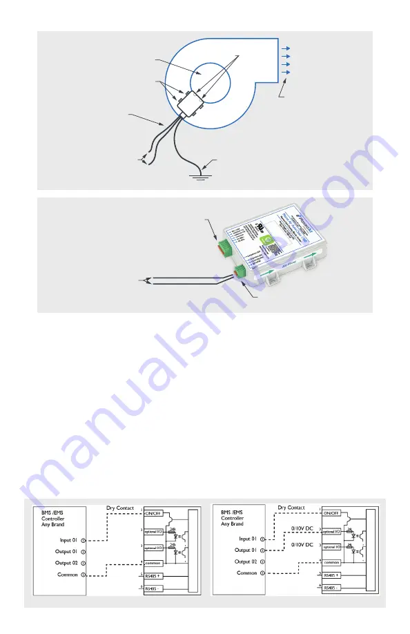
OPTIONAL BMS INTERFACE INSTALLATIONS
The AutoClean 1560 has the following optional wiring features (wiring and BMS
controller by others):
1.
BMS Compatible Status Output (On/Off Pin 1),
See Figure 4
. The status output is
connected to the input of a BMS controller that is setup to detect a dry contact.
When the unit is operating, the BMS will receive an On status.
2.
BMS Cleaning Cycle Command (Optional I/O Pin 2),
See Figure 5
. When On, the
unit will perform a cleaning cycle (should be normally Off and momentarily On).
The control point accepts a binary command.
• 0V DC for command Off (Normal Operation)
• 10V DC for command On (Momentary On will perform a single cleaning cycle)
3.
BMS On.Off Command (Optional I/O Pin 3),
See Figure 6
. When On, the unit will
stop operating. The control point accepts a binary command.
• 0V DC for command Off (Normal Operation)
• 10V DC for command On (Stop Operation)
FIGURE 2
FAN
DISCHARGE
FAN INLET
CONNECT TO GROUND
WHERE NECESSARY
CONNECT TO POWER
12-24V AC/DC
MOUNTING TABS
EMITTERS
6FT WIRING LEAD
INCLUDED IN
MOUNTING KIT
FIGURE 5
FIGURE 4
CONNECT TO POWER
12-24V AC/DC
BLACK AC/DC
RED AC/DC
POWER INLET FITTING
(6 foot leads by Plasma Air)
FIGURE 3
BAS CONTACT FITTING
(wiring by others)


