background image

5

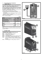
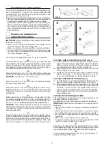
CONTROL PANEL (Fig. C)

Pos. 1 

Cutting current adjustment knob.

Pos. 2

  White LED - power supply on. When on the system 

is powered and ready for use.

Pos. 3 

Yellow LED with dual function and protection: THER-

MOSTAT and OVERCURRENT.

• 

THERMOSTAT function:

 this LED shines to indi-

cate that the overheating protection has cut in be-

cause the work cycle is not being followed. After 

several minutes the overheat cut-off rearms auto-

matically (and the yellow LED turns itself off) and 

the welder is ready for use again.

• 

OVERCURRENT function:

 this LED shines to 

indi cate that the overcurrent protection has cut in 

because the current has reached hazardous lev-

els. The machine stops automatically. Switch off 

the machine by turning the power supply switch 

(Pos. 4, Fig. B) to position “O” and switch it on 

again after at least 5 seconds.

Pos. 4

  GENERAL WARNING SIGNAL yellow LED. This 

switches on under the following conditions:


Switched on and flashing

•  External nozzle on the plasma torch missing or 

screwed on incorrectly.

•  Consumables (external nozzle, hood, electrode, 

etc.) on the plasma torch fitted incorrectly or worn.

•  In case of a faulty short-circuit on the plasma torch 

between the electrode and the hood.


Switched on and steady

•  No compressed air or insufficient pressure.

Pos. 5 

Red PLASMA CUTTING CYCLE CHECK LED. This 

LED switches on when the torch button is held down. 

The plant is therefore ready for the cutting operation. 

It switches off when the torch button is released.

Pos. 6

  Two position control:

• 

CUT -

 The switch must be moved to this position 

whenever you want to cut.

• 

AIR CHECK -

 The switch must be moved to this 

position whenever you want to carry out a test to 

check that air is present.

  Connection of plasma torch 

and ground wire

IMPORTANT: 

Before performing any operation regarding con­

nection of the torch and ground wire, disconnect the power to 

the system.

IMPORTANT: 

Do not connect to the Plasma equipment any 

other torch different from the standard supplied unes; the utili­

sation of other non suitable torches might be dangerous for 

the operator.

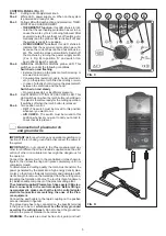
Connect the plasma torch to the centralised unit as shown in 

figure D, then screw the ring nut in place completely, until it is 

completely closed.

To obtain elevated cutting quality, the torch must transform the 

power generated by the plant into a high energy density plas-

ma jet, so that it can efficiently melt metal and guarantee suffi-

cient strength to remove the meted part from the cutting zone, 

impeding the formation of burrs. The torch is this a fundamen-

tal, indispensable component of the plasma cutting plant.

The standard supplied Plasma torch has special CEA elec-

trical connections in the central adaptor. Before fitting a 

new equipment, make sure that the torch central adaptor 

electrical connectios are matching the ones of the Plas-

ma equipment.

Connect the earth cable to the rapid coupling on the positive 

pole as indicated in figure D.

The ground wire has to be connected on the specific terminal 

to the piece to be cut, 

which must be effectively grounded 

as well as the cutting bench

. Do not connect the ground ter-

minal to the piece of material to be removed.

WARNING:

 The work area must be free of oil, paint, and rust!

1

2

3

4

5

6

FIG. C

FIG. D

Summary of Contents for SHARK 45

Page 1: ...W xxxxxx EN Operator s manual READ CAREFULLY CEA COSTRUZIONI ELETTROMECCANICHE ANNETTONI S p A C so E Filiberto 27 23900 Lecco Italy Tel 39 0341 22322 Fax 39 0341 422646 Cas Post P O BOX 205 e mail ce...

Page 2: ...ever you want to carry out a test to check that air is present A series of LEDs for indicating the cutting operating cycle and checking correct functioning of the plant Plasma torch with ignition of p...

Page 3: ...en the fused material flows through the groove and is not projected in the direction of the torch If the latter occurs cut ting speed has to be reduced The parameters that affect cutting are Electric...

Page 4: ...uses in the line with delays Table 2 Model SHARK 45 Single phase power supply 50 60 Hz V 115 15 230 15 Power input I2 Max kVA 4 8 5 5 Delayed fuse I2 100 A 25 16 Duty cycle X 40 C A 30 25 40 35 Mains...

Page 5: ...st be moved to this position whenever you want to cut AIR CHECK The switch must be moved to this position whenever you want to carry out a test to check that air is present Connection of plasma torch...

Page 6: ...f the post airflow phase the first time the pilot arc switches on this takes more time for the plant to carry out the necessary electronic and pneumatic tests 7 To start cutting press the torch button...

Page 7: ...r attention must be given to the solenoid valve and the air filter Although the air filters do not have an automatic conden sate drain it is good practice to clean the air filter insert from time to t...

Page 8: ...cally Switch off the machine by turning the power supply switch Pos 4 Fig B to position O and switch it on again after at least 5 seconds GENERAL WARNING SIGNAL yellow LED Pos 4 Fig C on and flashing...

Page 9: ...ltage 10 Before using the equipment you should carefully read the instructions included in this manual 11 Warning Risk of electric shock 12 Product suitable for free circulation in the European Commun...

Page 10: ...10 Wiring diagram 2101EA58...

Page 11: ...icambi LEGGERE ATTENTAMENTE EN Spare parts list READ CAREFULLY FR Liste pi ce de rechange LIRE ATTENTIVEMENT DE Ersatzteilliste SORGF LTIG LESEN ES Lista repuestos LEER ATENTAMENTE NL Onderdelenlijst...

Page 12: ...8296 468296 Adesivo lato connessione torcia Plasma Sticker central connection Plasma torch side 9 236621 236621 Attacco centralizzato torcia Plasma Central connection Plasma torch 10 461947 461947 Con...

Page 13: ...filter 17 404370 404370 Attacco rapido ingresso aria compressa Air inlet nipple 18 438400 438400 Manometro Manometer 19 352377 352377 Pannello posteriore Rear panel 20 427895 427895 Pressacavo linea...

Page 14: ...rch wiring 25 425944 425944 Elettrovalvola Air solenoid valve 26 453249 453249 Pressostato Pressostat switch 27 404898 404898 Basamento metallico Steel base 28 449586 449586 Telaio interno metallico S...

Page 15: ...Isolamento scheda inverter di potenza dal telaio Power inverter electric insulation from the chassis 35 377121 377121 Scheda elettronica controllo inverter Inverter control pcb 36 240241 240241 Indut...

Page 16: ...telling van reserveonderdelen Voor het bestellen van onderdelen duidelijk aangeven 1 Het codenummer van het onderdeel 2 Soort apparaat 3 Spanning en frequentie op het gegevensplaatje te vinden 4 Het s...

Page 17: ...CEA COSTRUZIONI ELETTROMECCANICHE ANNETTONI S p A C so E Filiberto 27 23900 LECCO ITALY Cas Post P O BOX 205 Tel 39 0341 22322 Fax 39 0341 422646 cea ceaweld com www ceaweld com...

Reviews: