7
Maintenance
ATTENTION:
Cut off the power supply to the equipment be
fore effecting any internal inspection.
SPARE PARTS
Original spares have been specifically designed for our equip-
ment.
The use of spares that are not original may cause variations
in the performance and reduce the safety level of the equip-
ment. We are not liable for damage due to use of spare parts
that are not original.
THE EQUIPMENT
As these systems are completely static except for the fan that
is, in any case, provided with self-lubricating bushes, only the
following operations are necessary:
• Periodic removal of accumulations of dirt and dust inside the
equipment using compressed air.
• Periodical inspection for worn cables or loose connections
that could cause overheating.
• Make sure the air circuit is completely free of any impurities
and that the connections are tight and free of any leaks. In
this regard, particular attention must be given to the solenoid
valve and the air filter.
• Although the air filters do not have an automatic conden-
sate drain, it is good practice to clean the air filter insert from
time to time.
Possible problems and remedies
The power line is the cause of most problems. In case of break-
downs proceed as follows:
1) Check the line value of the voltage
2) Check that the power cable is perfectly fastened to the plug
and mains switch
3) Make sure the fuses are not burnt or loose
4) Check the following for defects:
• The switch that powers the machine
• The wall socket for the plug
• The equipment power switch
NOTE:
Given the technical knowledge required for equipment
repair, we recommend, in case of faults, that you contact quali
fied personnel or our technical support service.
TROUBLESHOOTING TABLE
It is normally possible to find the cause of a breakdown through
the 4 warning LEDS located on the right hand side of the front
of the system. The first thing to do, therefore, is to check which
leds are on. Here below we are listing some of the possible
breakdowns that may occur on the system.
Summary of Contents for SHARK 45
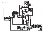
Page 10: ...10 Wiring diagram 2101EA58...


