background image

INSTRUCTIONS FOR INSTALLATION AND USE.

* NOTE:  For optimum installation, we recommend that you purchase an attachment kit.

1 - INSTALLATION

 (the help of a second person is recommended, when mounting the bracket holder )

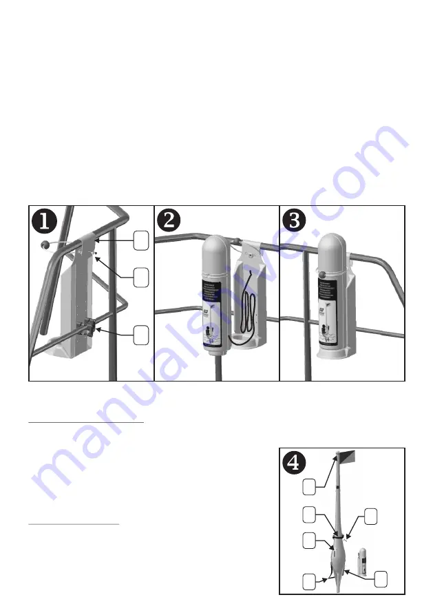
1.1 – Position the hook of the bracket holder over the top rail of the push pit (diagram 1-A)
1.2. - Remove canister from holder by pulling the blue elastic strap over the top of the canister.  Make 

sure the canister does not fall from the holder, as this will cause deployment. Also ensure the 
lanyard between the holder and the canister is not pulled, as this will also cause deployment.  A 
second person may hold the canister whilst the bottom of the bracket holder is secured by means 
of the two rail clamps in the fitting kit (diagram 1-B), Finally drill and fit the top rail security bolt 
(diagram 1-C), Do not over tighten this bolt as this will distort and damage the holder, only tighten 
to apply slight tension to the hook.

1.3 – Coil the 2m lanyard at the bottom of the holder and reinstall the canister on the holder (diagram 

2)

1.4 – Replace the securing strap on the canister (diagram 3). Ensure that the firing lanyard is not 

visible.

The Dan buoy is ready for use.

ENSURE SECURE FIXING OF THE BRACKET HOLDER AS THIS MAY PREVENT DEPLOYMENT IF 
NOT HELD SECURE

2 - INSTRUCTIONS FOR USE.

In the event of a man overboard emergency, release the canister from the holder by pulling the blue 
elastic strap over the top of the canister. (diagram 5)
Throw the canister forcefully, and complete, overboard in the 
direction of the man overboard (diagram 6). 
Deployment will be automatic; the lanyard with firing lever will 
remain attached to the holder.
If necessary the Dan buoy may be topped up by use of the red top 
up tube located on the mast.
The light on the Dan buoy is automatically activated upon inflation.

3 - CHARACTERISTICS

- flashing LED lamp 0.75cd/8h minimum (diagram 4-A)
- Co2 cylinder, 60gr (diagram 4-B)
- topping up adapter (diagram 4-C)
- whistle (diagram 4-D)
- the man overboard can hold on to the Dan buoy using the seating 
strap (diagram 4-E) and the securing strap (diagram 4-F)

- 4 -

IMPRESSION PANTONE 540

SUPPORT : OFFSET 80 GRS

C

B

A

D

B

F

C

E

A

61569_01.cdr
31 mars 2014

Summary of Contents for INFLATABLE DAN BUOY

Page 1: ...E DANBUOY HINCHABLE GB INFLATABLE DAN BUOY F PERCHE IOR GONFLABLE D AUFBLASBARE MARKIERUNGSBOJE NL OPBLAASBARE OPSPORINGSSTAAK S UPPBL SBAR DAN BUOY ASTA IOR GONFIABILE I ISAF ORC...

Page 2: ...ISAF ORC...

Page 3: ...3...

Page 4: ...2m lanyard at the bottom of the holder and reinstall the canister on the holder diagram 2 1 4 Replace the securing strap on the canister diagram 3 Ensure that the firing lanyard is not visible The Da...

Page 5: ...until the firing lever has been replaced as this will cause the cylinder to fire 4 6 Check that the cylinder housing seal in the inflator is in good condition Screw the new CO2 cylinder on to the infl...

Page 6: ...nd du support et r installer le coffret sur le support sch ma 2 1 4 Replacer l lastique de maintien du coffret sch ma 3 S assurer que le filin de percussion n est pas apparent La perche est pr te l em...

Page 7: ...le levier de d clenchement n ait t r introduit dans la t te de percussion car cela d clencherait la percussion 4 6 V rifier le bon tat du joint de logement de la bouteille dans la t te de percussion...

Page 8: ...r leicht anziehen damit der B gel unter Spannung steht Durch zu festes Anziehen k nnte der B gel rei en 1 3 die 2 m Leine im Boden der Halterung aufrollen und den Kasten wieder auf der Halterung anbri...

Page 9: ...in eingesetzt sein Ansonsten w rde sofort ein Aufpumpen erfolgen 4 6 Die Dichtung der Zylinderaufnahme im Ausl sekopf auf einwandfreien Zustand pr fen Von Hand einen neuen CO2 Zylinder auf den Ausl se...

Page 10: ...De 2m aan lijn onderaan de houder oprollen en de container weer op de houder plaatsen schema 2 1 4 Het bevestigingselastiek van de container weer terugplaatsen schema 3 Controleren dat de boei lijn n...

Page 11: ...stekingsmechanisme terug zolang de ontstekingshendel nog niet is teruggeplaatst Hierdoor zal de cilinder weer doorboord raken 4 6 Controleer de goede staat van de afdichtingshuls van de fles bovenop d...

Page 12: ...podr a distorsionar y da ar el soporte enroscar para dar una ligera tensi n al gancho 1 3 Recoger los 2m de cabo al fondo del soporte y reinstalar el malet n sobre el soporte esquema 2 1 4 Reemplazar...

Page 13: ...scar el cartucho en la cabeza de hinchado hasta que el percutor haya sido repuesto podr a ponerle fuego al cartucho 4 6 Comprobar el buen estado de conservaci n de la junta del cartucho en la cabeza d...

Page 14: ...er l nga linan inuti f stet och s tt fast beh llaren p f stet igen bild 2 1 4 F r tillbaka den elastiska snodden ver toppen p beh llaren bild 3 Se till att dan buoyens lina inte r synlig Nu r dan buoy...

Page 15: ...ld 7 OBS Skruva inte fast patronen f rr n uppbl snings mekanismen har termonterats eftersom detta leder till uppbl sning 4 6 Kontrollera packningen f r patronh llaren inuti uppbl sningsenheten Skruva...

Page 16: ...l gancio e quindi del supporto porta cilindro 1 3 Avvolgere i 2 m di cima al fondo del supporto e reinstallare il cilindro sul supporto disegno 2 1 4 Riposizionare l elastico di tenuta del cilindro di...

Page 17: ...ne per evitare di attivarla 4 6 Verificare il buon stato della guarnizione di alloggiamento della bombola nella testa di percussione Avvitare manualmente una nuova bombola di CO2 sulla testa di percus...

Page 18: ...18 TOP B A A 45cm 25cm 25cm 25cm 45cm B C D E B A C B C A B C...

Page 19: ...B 19 C B A A B A B A B From kit 63456...

Page 20: ...61569_01...

Reviews: