background image

RR 14 EVO 2-400 HYBRID

4.7. OPERATOR TRAINING

Operator training is based on the following:

1

Use and limitations of the controls in the basket, those on the ground and the emergency controls.

2

Knowledge and comprehension of this manual and the control signs, instructions and warnings affixed

to the machine.

3

Knowledge of all the work safety rules imposed by the employer and the laws in force, including training

in regard to the recognition and prevention of potential dangers present in the place of work, with

special attention to the specific job to be carried out.

4

Correct use of all mandatory personnel safety equipment, in particular the use of a safety helmet and

other fall-prevention equipment, such as a fall protection harness.

5

Sufficient knowledge of the mechanical working of the machine to be able to recognize actual or

potential breakdowns.

6

Use of the machine in adverse or unexpected conditions.

7

The best ways to operate the machine in the proximity of suspended obstructions, other moving

equipment and where there are obstructions, depressions, holes, sudden dips, etc. in the surface

supporting the machine.

8

The safest ways to avoid danger from bare electrical conductors.

9

Compliance with the requirements of a given task or a given machine application.

4.8. TRAINING SUPERVISION

The training must take place under the supervision of a qualified operator or supervisor, in an open area

without obstacles until the personnel under training have developed the ability to safely operate the lifting

platform in congested areas.

4.9. OPERATOR’S RESPONSIBILITIES

The operator must be informed that he has the responsibility and the authority to stop the machine in the case

of a breakdown or other conditions of reduced safety associated either with the machine or the work place and

to request instructions from the supervisor or the distributor of the product before proceeding further.

|

Note

At the time of delivery of the first unit and, successively, at the request of the user or his personnel, the

manufacturer or the distributor will provide qualified personnel to assist in the training of the operators.

4.10. WORKING CLOTHES

Always ensure you are wearing suitable work apparel before approaching the machine and/or starting work

with the machine.
When working with the machine the following precautions must be observed:

Wear close fitting apparel without loose appendages that may be caught up in moving and rotating

parts of the machine.

Wear clothes with appropriate fastening systems (buttons, zips, velcro, etc.) and always fasten them.

Sleeves must be close-fitting, belts properly fastened, bibs and braces correctly secured.

Do not wear scarves, ties, etc.

Do not wear sweaters, aprons and similar garments hanging on the shoulders or tied around the waist.

Do not wear necklaces, chains, bracelets, rings or watches.

Do not work with loose long hair, it must be pulled back.

4.11. WORK AREAS

Keep the work stations and transit areas clear of obstructions and clutter at all times.

English

49/150

Summary of Contents for RR 14 EVO 2-400 Hybrid

Page 1: ...2 2018 Edition 30 11 2019 Caution Before proceeding with all operations it is necessary to read and understand this manual in all its parts This manual must be stored for the entire life of the machin...

Page 2: ......

Page 3: ...CE MANUAL Model RR 14 EVO 2 400 Hybrid Serial number Client Year of manufacture ULTIMO BRANO TABELLA The contents of the present document cannot be used reproduced or transferred to third parties with...

Page 4: ...4 150...

Page 5: ...HINE OFF 2 5 2 PRODUCTION PAUSE 2 5 3 PROLONGED SHUTDOWN 3 TECHNICAL SPECIFICATIONS 3 1 TECHNICAL SPECIFICATIONS 3 2 OVERALL DIMENSIONS 3 3 RR 14 EVO 2 400 Hybrid WORKFLOW CHART 3 3 1 STABILIZATION ON...

Page 6: ...6 1 2 ACOUSTIC SIGNAL VISUAL SIGNAL 6 1 3 EMERGENCY BUTTON 6 1 4 INCLINATION CONTROL 6 1 5 TELESCOPIC BOOM AND EXTENSION HOME SENSORS 6 1 6 PANTOGRAPH BOOM HOME SENSORS 6 1 7 RAILWAY AXLES RAISED LOW...

Page 7: ...OWN 9 9 3 EXCESSIVE LOAD IN THE BASKET 9 9 4 CARRIAGE AND AXLES BLOCKED DUE TO ELECTRICAL BREAKDOWN 9 9 5 ELECTRIC PLANT BREAKDOWN 9 9 6 TOWING THE MACHINE ON RUBBER TYRES 9 9 7 TOWING THE MACHINE ON...

Page 8: ...E FILTER CARTRIDGES 11 18 REPLACEMENT OF THE FILTER CARTRIDGE OF THE CLOSED CIRCUIT PUMP 11 19 CLEANLINESS REPLACEMENT OF THE RETURN FILTER 11 20 CHECKING FOR WEAR AND WEAR PAD ADJUSTMENT 11 21 MAINTE...

Page 9: ...rms may be personalised 1 3 INTRODUCTION As our products are always in change as components of our suppliers some details could not match exactly those installed on Your machine type In such cases if...

Page 10: ...d should arise Keep the instructions for use and the attached documentation for future consultation 1 6 INTENDED USE In compliance with the machinery directive 2006 42 CE these machines must only be e...

Page 11: ...incorrect or inappropriate use of the machine such as Non conform method of use Use by personnel or operators not enabled Lack of attention in maintenance in controls during production process and in...

Page 12: ...y the manufacturer s technicians during the construction of the machine Service centre Authorised service center Place where you can interact with personnel authorised by us for the sale installation...

Page 13: ...se is to protect and support operators who need to work at a height Authorised service centre The place in which personnel authorised by the manufacturer carry out installation maintenance repair assi...

Page 14: ...ituation Extension widening Distance between the axis of the turret and the external edge of the basket Extensions Term used to describe the individual extension components that make up the telescopic...

Page 15: ...one on the ground 2 2 NAMEPLATE The machine identification plate is fixed on one side of the machine The following specifications are stamped on the plate 1 Model 2 Serial number 3 Year of manufactur...

Page 16: ...RR 14 EVO 2 400 HYBRID 2 2 2 MAIN SAFETY SIGNALS BRANO English 16 150...

Page 17: ...nder strain Points to use to fasten the machine to the means of transport GRUPPO Do not use water to extinguish fire on electrical parts BRANO Danger of projecting or falling objects BRANO Direction o...

Page 18: ...BRANO Hook up point for safety belts BRANO Manual emergency pump BRANO Read athe instruction manual BRANO Electric current service utility outlet Optional Generator GRUPPO Solenoid valve Name BRANO S...

Page 19: ...RR 14 EVO 2 400 HYBRID 2 2 3 INFORMATION SIGNALS BRANO English 19 150...

Page 20: ...Company name and logo BRANO Company name and logo BRANO Work field Note the sticker shown is purely indicative GRUPPO Work field Note the sticker shown is purely indicative GRUPPO Explains how to oper...

Page 21: ...as to obtain emergency handling of the superstructure BRANO Number of the railway axle BRANO Nameplate BRANO Nameplate BRANO Type of motor traction BRANO Maximum basket load BRANO Remind the operator...

Page 22: ...RR 14 EVO 2 400 HYBRID 2 2 4 MULTILINGUAL SAFETY SIGNALS BRANO English 22 150...

Page 23: ...RR 14 EVO 2 400 HYBRID BRANO BRANO Indicates caution during handling BRANO English 23 150...

Page 24: ...r and caution BRANO Indicates the filling outlet of a tank and its content BRANO this indicates the need to be particularly careful in order to avoid serious consequences which could harm the operator...

Page 25: ...VO 2 400 HYBRID First aid box BRANO The machine must be positioned with the control panel on the side closed to traffic BRANO Remind the operator to close the ladder when it is not used BRANO English...

Page 26: ...g cylinder 8 Scissor booms 9 telescopic boom lifting cylinder 10 Telescopic boom 11 Jib 12 Jib articulation cylinder 13 Basket 14 ground controls 15 Controls in the basket 16 Track cant inclination 17...

Page 27: ...RR 14 EVO 2 400 HYBRID 26 Main engine unit 27 Auxiliary engine unit GRUPPO English 27 150...

Page 28: ...n restarting the machine after production has been stopped due to any reason before proceeding check to ensure the machine has not been tampered with 2 5 1 SWITCHING THE MACHINE OFF Machine off means...

Page 29: ...On railways it is prohibited to leave the machine off completely with lights off GRUPPO 2 5 3 PROLONGED SHUTDOWN When the machine must remain inactive for a period exceeding 3 days e g forced absence...

Page 30: ...ine completely in rest position km h 5 External turning radius m 5 55 Internal turning radius m 2 85 Net installed power 41 kW 2450 rpm Measured sound power Lwa dB A 97 5 Guaranteed sound power Lwa dB...

Page 31: ...basket dimensions m 1 2 x 1 5 x 1 14 Maximum travelling speed during work km h 5 0 machine completely in rest position km h 19 Turning minimum radius m 40 Net installed power 41 kW 2450 rpm Measured...

Page 32: ...ANO Type 4 diesel engine liquid cooled times Number of cylinders 3 Exhaust gas treatment CEGR DOC DPF bore x stroke mm 84x88 Displacement l cm 1 464 Average speed of piston 3000 min 1 m s 8 8 compress...

Page 33: ...Starter 12V 2 2 kW 3CV 24V 3 0 kW 4 1CV Cool starting Temperature C 25 12V 32 24V Alternator recharge capacity at 3000 rpm 14V 60A 42A Generator charge power 110 14V 60 28V Battery capacity max Ah 12V...

Page 34: ...RR 14 EVO 2 400 HYBRID BRANO BRANO English 34 150...

Page 35: ...a minimum height of 15 mm from the track to a maximum height of 30 mm 3 3 RR 14 EVO 2 400 Hybrid WORKFLOW CHART Take into account the following information The workflow diagram is calculated using a m...

Page 36: ...RR 14 EVO 2 400 HYBRID 3 3 1 STABILIZATION ON ROAD WITH LOAD IN THE 80 400 kg BASKET Standard condition GRUPPO English 36 150...

Page 37: ...RR 14 EVO 2 400 HYBRID 3 3 2 STABILIZATION ON TRACKS WITH LOAD IN THE 80 400 kg BASKET Condition with standard and wide railway track gauge GRUPPO English 37 150...

Page 38: ...RR 14 EVO 2 400 HYBRID 3 3 3 SHIFTING ON TRACKS WITH LOAD IN BASKET 80 300 kg Condition with standard and wide railway track gauge Maximum shifting speed permitted 2 8 km h GRUPPO English 38 150...

Page 39: ...RR 14 EVO 2 400 HYBRID 3 3 4 SHIFTING ON TRACKS WITH LOAD IN BASKET 80 400 kg Condition with standard and wide railway track gauge Maximum shifting speed permitted 1 km h GRUPPO English 39 150...

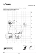
Page 40: ...g Maximum shifting speed permitted 5 km h Necessary condition scissor boom arm recovered Telescopic extension of the arm returned telescopic boom arm with a maximum tilt of 25 The turret s position wi...

Page 41: ...nobody is present in the area below the basket working area and prevent access if necessary It is forbidden to leave the machine set up differently than the original configuration and to leave the key...

Page 42: ...und from using the machine controls and warning them not to work walk or stop under the boom or the basket Cordon off the machine at ground level if necessary When the machine is to be relocated check...

Page 43: ...s the inspection procedure aimed at detecting parts that are defective damaged or incorrectly installed The list indicates the components to be inspected and the conditions to be examined Regular insp...

Page 44: ...that the refill plug is locked in position Check that the fuel lines are not damaged or leaking and that they are secured in position 4 4 3 BOOMS Check that the booms cylinders and pins are locked in...

Page 45: ...s clean and visible To keep them visible it is advisable to cover them when spraying paint or sand blasting Operating and maintenance manual Ensure that a copy of this manual is kept in the special co...

Page 46: ...d be locked in position the flexible pipes should have no visible damage or traces of leakage 5 Limiter micro switches Sensors correctly secured and efficient micro switches should be in good working...

Page 47: ...ble No corrosion no signs of leakage Efficiency of the rain guard drain plug 19 Turret rotation gears No loose or missing screws or nuts No damage visible appropriate lubrication No evidence of loosen...

Page 48: ...ing raising and lowering of the boom ground controls Rotate the general key switch to the OFF position None of the controls should be enabled not even the controls in the basket Start the auxiliary en...

Page 49: ...rea without obstacles until the personnel under training have developed the ability to safely operate the lifting platform in congested areas 4 9 OPERATOR S RESPONSIBILITIES The operator must be infor...

Page 50: ...achine and must be activated in the event of an immediate presumable danger Therefore familiarise yourself with the position of the various stop and emergency controls so that you can act immediately...

Page 51: ...ld on firmly to the designated supports 4 15 PERSONAL PROTECTIVE EQUIPMENT PPE When carrying out the normal working activity and during maintenance operations it must be guaranteed that the operators...

Page 52: ...ine Maintenance work on the machine must be performed in observance of all the safety indications given in the present publication Before performing maintenance work disconnect the machine from the en...

Page 53: ...the machine on and enables the ground controls The ground working position has priority over the basket position Switch turned to the right switches the machine on and enables the basket controls SA H...

Page 54: ...Optional When the switch is turned to the left the combustion motor is enabled When the switch is turned to the right the electric motor is enabled Optional SA87 Manual basket balancing keyswitch if r...

Page 55: ...ation switch Switch turned to the left machine enabled for normal work Switch turned to the right inhibits several movements output and lifting and travelling is enabled only if the machine is at rest...

Page 56: ...the combustion motor is enabled When the switch is turned to the right the electric motor is enabled Optional SA239 Basket control panel lighting switch Optional The switch turns on off the lights tha...

Page 57: ...SB93 Communication block button of the passage of oil between front and rear axle Press in case of rubber tyres slip during travelling Blocks the communication of the passage of oil between the front...

Page 58: ...ection c the telescopic elements retract Lever in direction d the telescopic elements exit GRUPPO JS3 Proportional joystick for the machine movement and steering Lever in direction a the machine trave...

Page 59: ...presence pedal dead man device Press to enable the machine movement controls I Caution To carry out the various movements always press the pedal and then activate the control requested GRUPPO 5 3 TOO...

Page 60: ...rward the front light switches on and the rear one remains off when travelling backward the rear light switches on and the front one remains off Both are off in the machine standstill phase HL105 Red...

Page 61: ...ckwards b Move forward YV121 122Available YV123 124 Measuring pole If present A Manual pump In the cases where there is a breakdown that determines a total block of the machine use the pump to make th...

Page 62: ...movement lever a Exit b Return YV134 135Jib movement lever a Opening b Closing YV136 137Basket movement lever a counterclockwise rotation b clockwise rotation YV138 139Basket manual balancing lever a...

Page 63: ...rved 6 1 1 BASKET LOADING CELL Measures the load inside the basket The red indicator light and the intermittent acoustic signal warn that the maximum permitted load in the basket has been exceeded Exc...

Page 64: ...machine reset The work conditions The safety conditions The emergency stop device by twisting the button head in the direction shown by the arrows marked on it Check the efficiency of the safety devic...

Page 65: ...clination of the machine When the inclination 3 on wheels are exceeded they are displayed on the machine control system GRUPPO 6 1 5 TELESCOPIC BOOM AND EXTENSION HOME SENSORS These detect the complet...

Page 66: ...ravelling combined with the telescopic boom sensors at rest and extension retracted GRUPPO 6 1 7 RAILWAY AXLES RAISED LOWERED SENSORS The sensor SQ48 detects the raised position of the railway axle N1...

Page 67: ...t triggering machine s alarms in order to prevent the basket colliding with the tracks GRUPPO 6 1 9 MANUAL EMERGENCY PUMP The machine has a manual emergency pump in the event that there is a fault whi...

Page 68: ...PPO 6 1 11 ROTATION CHECK The rotation of the turret is 360 non continuous approx 180 on the right hand side and approx 180 on the left hand side Checking the rotation of the turret is carried out usi...

Page 69: ...RR 14 EVO 2 400 HYBRID BRANO English 69 150...

Page 70: ...RR 14 EVO 2 400 HYBRID BRANO BRANO English 70 150...

Page 71: ...are correctly inserted The steering block allows to lower the railway wheels rear axle and travelling on the railway GRUPPO 6 1 14 FIRE ENTINGUISHER CO2 2 kg 34B IF PRESENT The machine has a fire exti...

Page 72: ...t been damaged It has the relative maintenance tag correctly filled out Any faults have been immediately corrected Check overhaul and test Checks and maintenance should only be carried out by qualifie...

Page 73: ...PPO 6 1 16 OIL SPILL PREVENTION KIT IF PRESENT The machine is equipped with an oil spill prevention kit GRUPPO 6 1 17 LADDER The machine has a ladder to make it easier to access the control board when...

Page 74: ...visual level indicator A and or and electronic indicator B I Caution The equipment is built according to applicable laws GRUPPO 6 1 19 BATTERY CUT OFF SWITCH In A on position it enables engine operat...

Page 75: ...ty harness in the basket structure Hooking the device prevents the operator from being thrown out of the basket due to unforeseeable conditions Note The operator in the basket must compulsorily wear a...

Page 76: ...UMENT FOR MEASUREMENT AND EARTHING OF THE RESIDUAL ENERGY The machine can be fitted with the pole 3064PB Having reached the work point lift the pole and place it in contact with the power line The pol...

Page 77: ...RR 14 EVO 2 400 HYBRID 7 3 NIGHTIME LIGHTING KIT The machine can be fitted with supplementary lighting to ensure greater visibility GRUPPO English 77 150...

Page 78: ...s to walk or stand under or in the vicinity of suspended loads lift loads to the indispensable minimum height move loads close to the ground at low speed and taking care to avoid impacts and jolts kee...

Page 79: ...ated and with a tensioning force of the collars that is lower than the appropriate one In order to stabilize the base of the machine it is necessary to hook the collars to the preset A point GRUPPO 8...

Page 80: ...ort vehicle with the aid of a crane or overhead crane In this case the machine will be lifted by appropriate capacity chains or wire ropes by hooking it to the perforated disks as subsequently illustr...

Page 81: ...king conditions the operator should adopt the safest and most suitable operational sequence 9 2 START STOP ENGINE The engine start and stop actions are possible from the control board on the ground an...

Page 82: ...EVO 2 400 HYBRID 9 2 2 STOP MAIN ENGINE Check that the machine configuration is in maximum safety conditions Turn the selector SA71 or SA70 to the left to switch the main engine off GRUPPO English 82...

Page 83: ...the centre to enable the engine and then to the right to switch the engine on I Caution If the main engine is on turning the selector SA36 or SA36A at the centre to enable the auxiliary engine the mai...

Page 84: ...travelling can only be performed from the basket position In the movement phase the machine can exceed gradients of up to Longitudinal gradient 16 29 Transversal gradient I Caution To exceed the ascen...

Page 85: ...position that is used to perform the operations The engine is running see start stop engine I Caution To perform travel operations check on the control system display that basket travel is enabled GR...

Page 86: ...asket position SA37 turned onto the basket position Climbing into the basket Check that the sliding bar which protects the opening of the basket is closed and positioned correctly Attach the safety be...

Page 87: ...ted You can also move at a low speed with the boom extended but only at an angle greater than 70 and a load in the basket up to 300 kg With a load between 300 kg and 400 kg moving is only allowed with...

Page 88: ...he ground If necessary move and align the axle N1 with the tracks with the help of the steering wheel Insert the steering wheel locking pins Completely lower the railway axle N2 Completely lower the r...

Page 89: ...cannot move On Off tracking will only take place at a designated RRAP Manoeuvre the machine so that the rail wheels are aligned as accurately as possible with the tracks Lower the railway axle startin...

Page 90: ...ravelled to the RRAP with OLE Key in restricted position booms fully down and fly boom within restricted area If necessary raise the jib so that the bucket does not touch the tracks Completely raise t...

Page 91: ...position See control panel on the ground If it becomes necessary to move the aerial part from the ground it is necessary to move the switch SA37 to ground position See control panel on the ground Clim...

Page 92: ...l part to be moved with the aim of bringing the operator in the basket back to the ground and the machine to be closed i Danger When making an emergency manoeuvre pay particular attention to the safet...

Page 93: ...Boom blocked because the basket is overloaded Remove the excess load in order to be able to work again with all possible movements Boom blocked because of interference from external objects Using the...

Page 94: ...the pin A clockwise until it remains in the lowered positioned and is blocked to bypass the valve YV90 Solenoid dump valve Break the seal press and turn the pin B clockwise until it remains in the lo...

Page 95: ...the pull start cord Break the seal pull and turn the pin B to allow the passage of fuel Pull the engine switch on cord C Use the distributors of the aerial movements or trolley movements with the safe...

Page 96: ...are electrical faults GRUPPO To move the overhead part Break the seal press and turn the pin A clockwise until it remains in the lowered positioned and is blocked to bypass the valve YV125 Close the o...

Page 97: ...B clockwise until it remains in the lowered positioned and is blocked to bypass the valve YV110 Activate the distributor levers C for truck movement See chapter cart emergency controls Having complet...

Page 98: ...he valves YV92 YV92A In this way the system for blocking the oscillating axle is cut out and you can continue with the machine towing procedures in the required configuration GRUPPO Unscrew the centra...

Page 99: ...o a service centre for the necessary repairs and to restore the seals GRUPPO 9 9 7 TOWING THE MACHINE ON RAILWAY WHEELS i Danger Risk of derailment If the machine is being towed on rubber tyres or on...

Page 100: ...ing performed these operations contact an authorised after sales centre for the due repairs In these conditions the machine is not braked I Caution After any operation where it was necessary to remove...

Page 101: ...A in normal conditions To activate the valve proceed as follows GRUPPO 1 Break the valve hood seal and remove it The pawl B is in normal conditions GRUPPO 2 Unscrew the pawl B to bypass the valve A un...

Page 102: ...ation concerning the problem detected 10 2 MAINS DEFECTS I Caution The operations reported in this chapter are to be done exclusively by the authorised shops The auxiliary engine does not start althou...

Page 103: ...Fasten fittings Withdraw valves Check the pump ULTIMO BRANO TABELLA Metal participles founded in the oil filters Causes Remedy Parts of the oleo dynamic system are damaged Find the breakdown parts rep...

Page 104: ...reaker has tripped Restore the magnet circuit breaker Q1 positioned inside the control board on the ground taking it from OFF to ON ULTIMO BRANO TABELLA Control valve lever which stops or which comes...

Page 105: ...one by a specialized workshop i Danger All maintenance work must be done with the machine inoperative in other words with the motor switched off the electrical voltage to the panels cut off and the ma...

Page 106: ...oppage in a clearly visible manner with a sign placed on the control panel reading WORK IN PROGRESS Work in progress operation prohibited GRUPPO I Caution Replace the components ONLY with ORIGINAL PAR...

Page 107: ...rst expiration date Check all Cage Controls 250 h 1 Two month period Check all Ground Controls 250 h 1 Two month period Check Auxiliary Systems 250 h 1 Two month period Condition of RRV Self propelled...

Page 108: ...product check 1000 h Six Months Coolant replacement Heat exchanger 2000 h Annually 11 5 4 MAIN MOTOR I Caution Use lubricants oils or grease recommended by the manufacturer or with similar chemical ph...

Page 109: ...Cage Assembly 250 h 1 Two month period Cage Entry Gate 250 h Two month period Cage Rotate device 250 h Two month period Check the conditions of the control panel 500 h Three months 1 After the first...

Page 110: ...r oil leaks 500 h 1 Three months Analyse hydraulic oil 500 h Three months Replace tank return filter 500 h Three months Replace in line 20 micron filters 500 h Three months Check circuit pressures 500...

Page 111: ...ors efficiency control 250 h Two month period Check the functioning of all the lights 250 h Two month period Check horn 250 h Two month period Check Bearing End Float 250 h Two month period Check back...

Page 112: ...pack the bearings within the tolerance See the maintenance manual SKF 3 The height of the flange must comply with the Norm relating to the State in which the platform is certified The condition of th...

Page 113: ...f along the entire circumference of the wheel the gauge remains in contact only with the profile of the flange Use a go no go caliper compliant to the wheel installed to check the height of the flange...

Page 114: ...enance in progress sign 11 8 CLEANING After every trip and every intervention clean carefully the equipment joints pins sliding pads Keep handles and decking free of oil grease and dirt to minimise th...

Page 115: ...hine must be clearly legible If deterioration is found request a replacement by contacting the manufacturer s spare parts service directly 11 9 GREASING Using the pump lubricator put lubricating greas...

Page 116: ...RR 14 EVO 2 400 HYBRID 11 9 1 GREASING POINTS DIAGRAM The illustration below shows the grease nipples Inject grease into all the grease nipples GRUPPO English 116 150...

Page 117: ...f the level is visible in the indicator and is between the min and max points on the level indicator 11 12 REPLACE THE HYDRAULIC OIL i Danger Oil at high temperature Risk of burns Before realising the...

Page 118: ...he tank D has been filled make sure that the taps B are open and reseal them GRUPPO 10 Open the cap F e put oil into it reaching the right level I Caution Use the hydraulic oil with the same character...

Page 119: ...wheels 3 Turn the wheel with caps positioned as shown in the figure and remove the top one Unscrew cap D GRUPPO 4 Turn the wheel C slowly until the presence of oil is detected but does not leak out T...

Page 120: ...3 I Caution Prepare a vessel collecting lubricating oil Dispose of the used oil in the terms and methods prescribed by the environmental Standards in force 9 Turn the wheel C until the hole F is in th...

Page 121: ...tyres 3 Turn the wheel with caps positioned as shown in the figure and remove the top one Unscrew cap D GRUPPO 4 Turn the wheel C slowly until the presence of oil is detected but does not leak out Th...

Page 122: ...I Caution Prepare a vessel collecting lubricating oil Dispose of the used oil in the terms and methods prescribed by the environmental Standards in force 9 Turn the wheel C until the hole F is in the...

Page 123: ...ection GRUPPO 11 16 LUBRICANTS TABLE I Caution All maintenance work must be done with the motor switched off and the machine in the rest position I Caution Do not use oil grease other than that recomm...

Page 124: ...ing the same degree of filtering 20 I Caution Before putting back the filter grease the seal GRUPPO 11 18 REPLACEMENT OF THE FILTER CARTRIDGE OF THE CLOSED CIRCUIT PUMP Move the machine into the rest...

Page 125: ...Uscrew the cover C of the filter Extract the filter and clean or replace it with one with the same filtering capacity I Caution Lubricate and check the position of the seal between the cover and the...

Page 126: ...work I Caution Always wear safety goggles mask and gloves when performing operations on the batteries Follow the instructions given in the manufacturer s manual The batteries do not need maintenance...

Page 127: ...RR 14 EVO 2 400 HYBRID 11 22 CHECK TIGHTENING 1 Joints ring nuts 2 Rubber tyres and railway wheels screws 3 Slewing ring screws GRUPPO English 127 150...

Page 128: ...6 8 8 10 9 12 9 6 D 8 G 10 K 12 K 6 D 8 G 10 K 12 K M4x0 7 222 394 554 665 0 17 0 31 0 43 0 52 M5x0 8 357 635 895 1070 0 33 0 60 0 84 1 01 M6x1 507 902 1270 1520 0 58 1 03 1 46 1 75 M7x1 728 1300 1820...

Page 129: ...0 32 00 57 50 80 50 97 00 M24x2 9650 17200 24200 29000 41 00 73 50 103 00 124 00 M27x2 12500 22300 31300 37500 60 00 107 00 150 00 180 00 M30x2 15700 27800 39200 47000 83 00 147 00 208 00 250 00 ULTIM...

Page 130: ...buttons work correctly When the machine is on press one of the mushroom head buttons and attempt to perform a manoeuvre This should be prohibited If it is activated anyway switch the machine off and c...

Page 131: ...engine starter motor F3 30 Electric panel power supply protection F4 30 Electric panel power supply protection ULTIMO BRANO TABELLA 11 27 PLACING THE MACHINE OUT OF SERVICE FOR A PROLONGED PERIOD OF...

Page 132: ...hine organs and transfer it to a safe place where nobody can gain access to it Use suitable lifting means as indicated in the Transport section of the Lifting systems chapter Break the latches on the...

Page 133: ...ugh sheets in the record add other sheets as necessary photocopying them or drawing them up in the same way as the ones present On the additional sheets the user will indicate the type of platform the...

Page 134: ...ions have been recorded in this Register The Seller ULTIMO BRANO TABELLA The Buyer ULTIMO BRANO TABELLA SUCCESSIVE CHANGES OF OWNERSHIP Date ULTIMO BRANO TABELLA The ownership of the WORK PLATFORM ULT...

Page 135: ...ions have been recorded in this Register The Seller ULTIMO BRANO TABELLA The Buyer ULTIMO BRANO TABELLA SUCCESSIVE CHANGES OF OWNERSHIP Date ULTIMO BRANO TABELLA The ownership of the WORK PLATFORM ULT...

Page 136: ...ions have been recorded in this Register The Seller ULTIMO BRANO TABELLA The Buyer ULTIMO BRANO TABELLA SUCCESSIVE CHANGES OF OWNERSHIP Date ULTIMO BRANO TABELLA The ownership of the WORK PLATFORM ULT...

Page 137: ...to the Firm Company ULTIMO BRANO TABELLA It is hereby certified that at the date mentioned above the technical specifications dimensions and functions of the WORK PLATFORM described in this manual co...

Page 138: ...frequency of the operation A if necessary B day C week D month E two month period F three months G six months H year NO INTERVENTION Periodicity of maintenance Work hours Date Description of action U...

Page 139: ...iption of action ULTIMO BRANO TABELLA Signature NO INTERVENTION Periodicity of maintenance Work hours Date Description of action ULTIMO BRANO TABELLA Signature NO INTERVENTION Periodicity of maintenan...

Page 140: ...VENTION Periodicity of maintenance Work hours Date Description of action ULTIMO BRANO TABELLA Signature NO INTERVENTION Periodicity of maintenance Work hours Date Description of action ULTIMO BRANO TA...

Page 141: ...VENTION Periodicity of maintenance Work hours Date Description of action ULTIMO BRANO TABELLA Signature NO INTERVENTION Periodicity of maintenance Work hours Date Description of action ULTIMO BRANO TA...

Page 142: ...BRANO TABELLA Replaced element ULTIMO BRANO TABELLA Description of new element ULTIMO BRANO TABELLA Manufacturer ULTIMO BRANO TABELLA Supplied by ULTIMO BRANO TABELLA Reason for the replacement ULTIMO...

Page 143: ...BRANO TABELLA Replaced element ULTIMO BRANO TABELLA Description of new element ULTIMO BRANO TABELLA Manufacturer ULTIMO BRANO TABELLA Supplied by ULTIMO BRANO TABELLA Reason for the replacement ULTIMO...

Page 144: ...BRANO TABELLA Replaced element ULTIMO BRANO TABELLA Description of new element ULTIMO BRANO TABELLA Manufacturer ULTIMO BRANO TABELLA Supplied by ULTIMO BRANO TABELLA Reason for the replacement ULTIMO...

Page 145: ...BRANO TABELLA Replaced element ULTIMO BRANO TABELLA Description of new element ULTIMO BRANO TABELLA Manufacturer ULTIMO BRANO TABELLA Supplied by ULTIMO BRANO TABELLA Reason for the replacement ULTIMO...

Page 146: ...BRANO TABELLA Replaced element ULTIMO BRANO TABELLA Description of new element ULTIMO BRANO TABELLA Manufacturer ULTIMO BRANO TABELLA Supplied by ULTIMO BRANO TABELLA Reason for the replacement ULTIMO...

Page 147: ...BRANO TABELLA Replaced element ULTIMO BRANO TABELLA Description of new element ULTIMO BRANO TABELLA Manufacturer ULTIMO BRANO TABELLA Supplied by ULTIMO BRANO TABELLA Reason for the replacement ULTIMO...

Page 148: ...RR 14 EVO 2 400 HYBRID 14 ENCLOSED DOCUMENTATION 14 1 HYDRAULIC SYSTEM GRUPPO English 148 150...

Page 149: ...RR 14 EVO 2 400 HYBRID 14 2 ELECTRICAL SYSTEM GRUPPO English 149 150...

Page 150: ...LARATION The EC statement of conformity is the document signed by the manufacturer which guarantees and certifies that the machine complies with all the safety regulations The EC statement of conformi...

Reviews: