background image

For Customer Service Call
800.333.8519 (U.S.A.) or
541.955.9199 (International)

Manufactured by Krauss Craft, Inc.
www.playcraftsystems.com

GYRO-POD SPINNER RV

INSTALLATION INSTRUCTIONS

Rev B

1/5/2017

RV-1974

Page 6 of 8

For Customer Service Call
800.333.8519 (U.S.A.) or
541.955.9199 (International)

Manufactured by Krauss Craft, Inc.
www.playcraftsystems.com

GYRO-POD SPINNER RV

INSTALLATION INSTRUCTIONS

Rev B

1/5/2017

RV-1974

Page 6 of 8

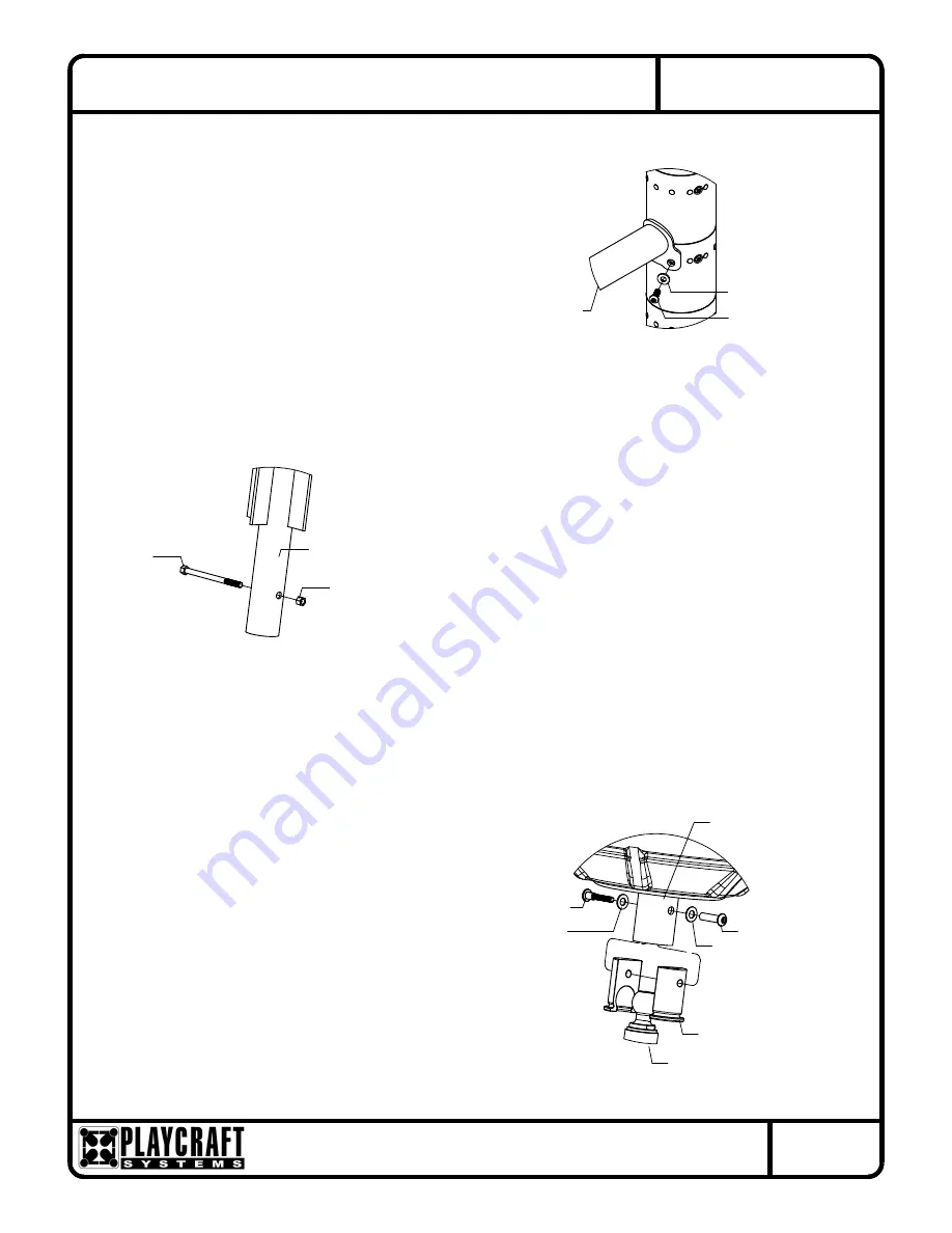
3/8" x 1" Button 

Figure 1.2

TOP FRAME

Head Bolt

3/8" x 7/8" O.D. 
Thick Washer

FIGURE 6

GYRO-POD LEG

Hex Bolt

3/8" x 5-1/2"  

3/8" Hex Nut

SOCKET HALF

Shoulder Bolt

3/8" x 2" Barrel Nut

1/2" SAE Washer

1/2" SAE Washer

3/8" x 2-1/2" 

BEARING HUB

GYRO-POD 

BALL JOINT 

GYRO-POD LEG

Figure 1.3

Step 8


Install footing pin into Gyro-Pod Leg as shown 
in Figure 6. (See Note A)

Step 9


Attach Gyro-Pod Leg to Gyro-Pod Bearing Hub 
as shown in Figure 1.3. (See Note A)

Step 7


Refer to Footing detail and remove required Hole Plugs. 
Attach Top Frame to post as shown in Figure 1.2.
(See Note A)

Summary of Contents for Gyro-Pod Spinner RV

Page 1: ...e for the fall height of A Use liquid thread lock such as Loctite with all threaded hardware Important Liquid thread lock prior to curing helps to eliminate the common problem of thread seizure in sta...

Page 2: ...ting Detail for depth and details Footing depth must be adjusted to compensate for the depth thickness requirements of selected safety surfacing See Section 06 1 of the Installation Manual Footing Det...

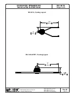
Page 3: ...55 9199 International Manufactured by Krauss Craft Inc www playcraftsystems com GYRO POD SPINNER RV INSTALLATION INSTRUCTIONS Rev B 1 5 2017 RV 1974 Page 3 of 8 RV 1974 Footing Layout RV 1974 STRT Foo...

Page 4: ...Page 4 of 8 FIGURE 2 GYRO POD HANDRAIL 3 8 x 1 1 4 Button Head Bolt Washer 3 8 Lock Nut 3 8 x 1 O D Washer 3 8 x 1 O D GYRO POD BEARING HUB GYRO POD BEARING HUB FIGURE 3 Button Head Bolt 3 8 x 1 1 2 W...

Page 5: ...B 1 5 2017 RV 1974 Page 5 of 8 3 8 x 1 O D Washer FIGURE 5 Washer 3 8 x 1 O D Head Bolt 3 8 x 3 4 Button END GYRO POD RING GYRO POD END GYRO POD Head Bolt 3 8 x 3 4 Button Washer 3 8 x 1 O D 3 8 x 1...

Page 6: ...S Rev B 1 5 2017 RV 1974 Page 6 of 8 3 8 x 1 Button Figure 1 2 TOP FRAME Head Bolt 3 8 x 7 8 O D Thick Washer FIGURE 6 GYRO POD LEG Hex Bolt 3 8 x 5 1 2 3 8 Hex Nut SOCKET HALF Shoulder Bolt 3 8 x 2 B...

Page 7: ...wn Place Gyro Pod Leg into footing hole and attach Step 10 Step 11 Apply Gyro Pod Warning Label where visible to users as shown in Figure 7 Step 12 Fully tighten all fasteners according to the TIGHTEN...

Page 8: ...e Play Tuff coated after fabrication GYRO POD RING PLATE Shall be made from precision cut 1 4 thick sheet steel The Gyro Pod Ring Plate shall have a multi stage baked on powder coat finish GYRO POD EN...

Reviews: