background image

For Customer Service Call
800.333.8519 (U.S.A.) or
541.955.9199 (International)

Manufactured by Krauss Craft, Inc.
www.playcraftsystems.com

GYRO-POD SPINNER RV

INSTALLATION INSTRUCTIONS

Rev B

1/5/2017

RV-1974

Page 7 of 8

For Customer Service Call
800.333.8519 (U.S.A.) or
541.955.9199 (International)

Manufactured by Krauss Craft, Inc.
www.playcraftsystems.com

GYRO-POD SPINNER RV

INSTALLATION INSTRUCTIONS

Rev B

1/5/2017

RV-1974

Page 7 of 8

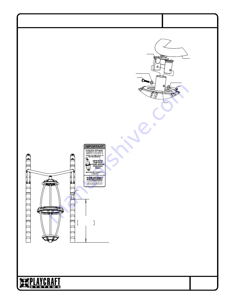
in Figure 1.4. (See Notes A, B, C & D)

Gyro-Pod Bearing Hub to Top Frame as shown 

Place Gyro-Pod Leg into footing hole and attach 


Step 10

Step 11


Apply Gyro-Pod Warning Label where visible to 
users as shown in Figure 7.

Step 12


Fully tighten all fasteners according to the 
"TIGHTENING TORQUE FOR HARDWARE" 
section of the Installation Manual.

Step 13


Plumb and level entire component. Pour 
concrete into footing hole. Allow at least 72 
hours to cure before using this equipment.
(See Notes B, C & D)

Step 14


Place required protective surfacing under and 
around Gyro-Pod Spinner. (See Note E)

TOP FRAME

3/8" x 2-1/2" 

SOCKET HALF

BALL JOINT 

Shoulder Bolt

1/2" SAE Washer

1/2" SAE Washer

3/8" x 2" Barrel Nut

GYRO-POD 
BEARING HUB

Figure 1.4

Gyro-Pod Spinner
Warning Label

(Finish Grade)

FIGURE 7


47"

1194mm


Summary of Contents for Gyro-Pod Spinner RV

Page 1: ...e for the fall height of A Use liquid thread lock such as Loctite with all threaded hardware Important Liquid thread lock prior to curing helps to eliminate the common problem of thread seizure in sta...

Page 2: ...ting Detail for depth and details Footing depth must be adjusted to compensate for the depth thickness requirements of selected safety surfacing See Section 06 1 of the Installation Manual Footing Det...

Page 3: ...55 9199 International Manufactured by Krauss Craft Inc www playcraftsystems com GYRO POD SPINNER RV INSTALLATION INSTRUCTIONS Rev B 1 5 2017 RV 1974 Page 3 of 8 RV 1974 Footing Layout RV 1974 STRT Foo...

Page 4: ...Page 4 of 8 FIGURE 2 GYRO POD HANDRAIL 3 8 x 1 1 4 Button Head Bolt Washer 3 8 Lock Nut 3 8 x 1 O D Washer 3 8 x 1 O D GYRO POD BEARING HUB GYRO POD BEARING HUB FIGURE 3 Button Head Bolt 3 8 x 1 1 2 W...

Page 5: ...B 1 5 2017 RV 1974 Page 5 of 8 3 8 x 1 O D Washer FIGURE 5 Washer 3 8 x 1 O D Head Bolt 3 8 x 3 4 Button END GYRO POD RING GYRO POD END GYRO POD Head Bolt 3 8 x 3 4 Button Washer 3 8 x 1 O D 3 8 x 1...

Page 6: ...S Rev B 1 5 2017 RV 1974 Page 6 of 8 3 8 x 1 Button Figure 1 2 TOP FRAME Head Bolt 3 8 x 7 8 O D Thick Washer FIGURE 6 GYRO POD LEG Hex Bolt 3 8 x 5 1 2 3 8 Hex Nut SOCKET HALF Shoulder Bolt 3 8 x 2 B...

Page 7: ...wn Place Gyro Pod Leg into footing hole and attach Step 10 Step 11 Apply Gyro Pod Warning Label where visible to users as shown in Figure 7 Step 12 Fully tighten all fasteners according to the TIGHTEN...

Page 8: ...e Play Tuff coated after fabrication GYRO POD RING PLATE Shall be made from precision cut 1 4 thick sheet steel The Gyro Pod Ring Plate shall have a multi stage baked on powder coat finish GYRO POD EN...

Reviews: