background image

IMPORTANT NOTES: Read First

For Customer Service Call
800.333.8519 (U.S.A.) or
541.955.9199 (International)

Manufactured by Krauss Craft, Inc.
www.playcraftsystems.com

RAMP R5

Rev G

6/5/2010

R5-1208

Page 1 of 6

NOTE: Ramp with Rails shown. 
Ramp with Walls and Flat Ramp 
with Walls will vary slightly, but 
do not affect the assembly.

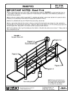
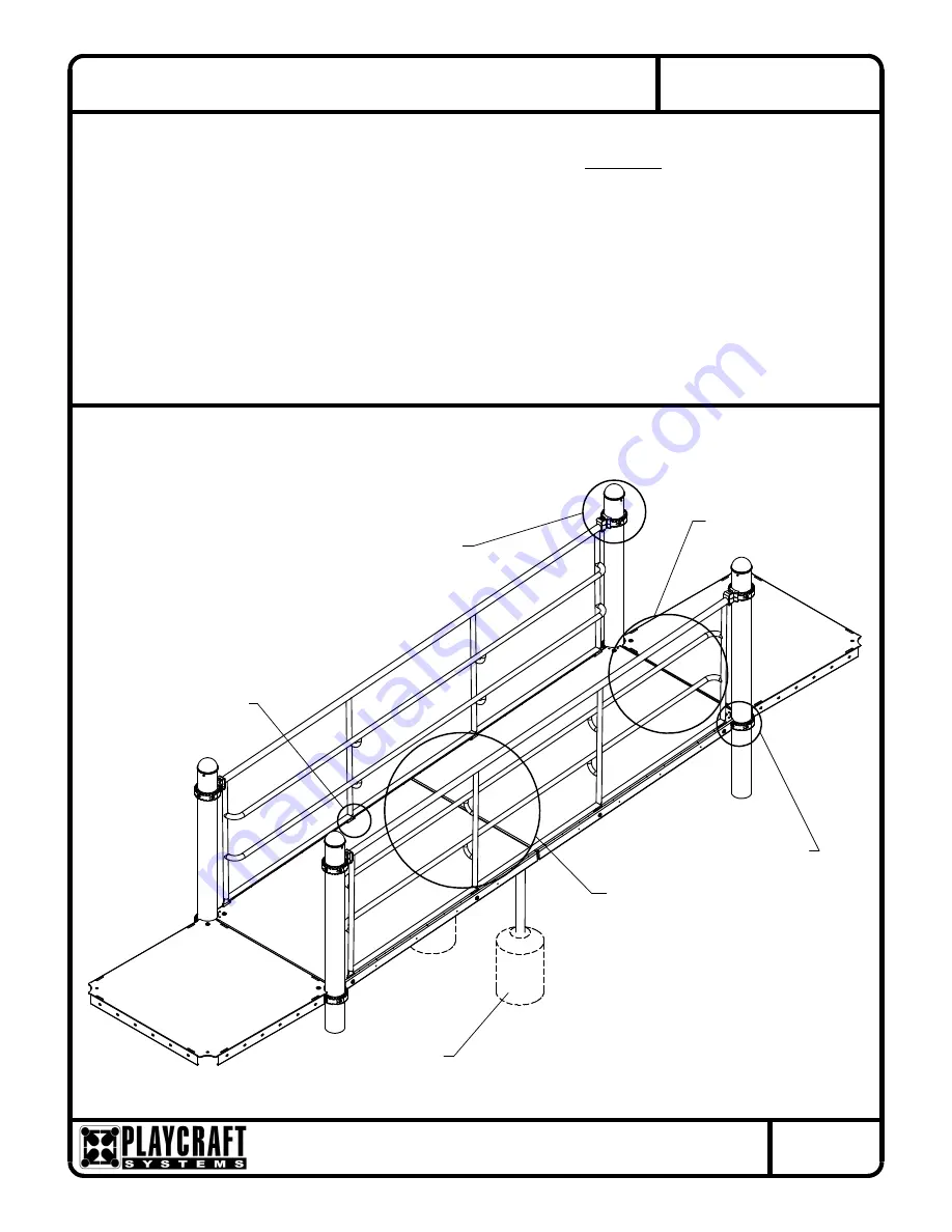
Figure 1.2

Sections R5-09 Collars

The Handbook for Public Playground Safety, Publication #325 at www.CPSC.gov for the surfacing appropriate for 

FIGURE 1

Ramp w/ Rails R5

The Gap Between the Top of the Ramp and the  Bottom of the Wall should be no more than 1". Please refer to 

the Footing Detail View.

(E) 

the fall height of the equipment or consult you surfacing supply representative.

Figure 1.5

See Footing Detail

Figure 1.3

(A) Use liquid thread lock (such as Loctite

®

) with all threaded hardware. Important: Liquid thread lock (prior to 

curing) helps to eliminate the common problem of "thread seizure" in stainless steel hardware by serving as a 
lubricant during assembly.

(B) Do not pour concrete until the equipment is completely assembled, leveled and plumbed. Concrete must be 
allowed to cure completely before using the equipment (at least 72 hours).

(C) Refer to Installation Manual for R5-09 Collars assembly instructions.

(D) Use appropriate compliant protective surfacing and adjust footing depths accordingly. See free publication - 

Figure 1.4

See Installation Manual 

Figure 1.1

Summary of Contents for Ramp R5

Page 1: ... to the Footing Detail View E the fall height of the equipment or consult you surfacing supply representative Figure 1 5 See Footing Detail Figure 1 3 A Use liquid thread lock such as Loctite with all threaded hardware Important Liquid thread lock prior to curing helps to eliminate the common problem of thread seizure in stainless steel hardware by serving as a lubricant during assembly B Do not p...

Page 2: ...inage Concrete Footing Footing Anchor 2b Stone drain rock Undisturbed Soil Optional Filter Fabric Over Footing depth must be adjusted to compensate for the depth thickness requirements of selected safety surfacing See Section 06 1 of the Installation Manual 18 457mm 27 686mm 39 Top of Deck to Top of Collar 991mm 39 Top of Deck to Top of Collar 991mm 1 Max See Note E UPPER DECK Step 1 Refer to Foot...

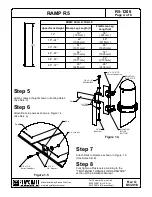
Page 3: ... footing holes Attach Ramps and Ramp Legs as shown in Figure 1 3 See Note A NOTE Use Ramp Legs that correspond to deck heights See Ramp Leg I D Table BLOCK TOP Barrel Nut 3 8 X2 Washer 1 2 SAE Button Head Bolt 3 8 x 2 1 2 O D Washer 3 8 x 1 BOTTOM BLOCK MOUNTING MOUNTING RAMP Figure 1 1 Lock Nut Figure 1 2 Button Head Bolt 3 8 x 1 1 4 3 8 Lock Nut RAMP Lock Nut 3 8 Button Head Bolt 3 8 x 1 1 2 3 8...

Page 4: ...Length X 12 30 761mm 36 914mm 18 24 42 1066mm 48 1218mm 30 36 54 1371mm 60 1520mm 42 48 66 1675mm 72 1828mm 54 60 78 1977mm 84 2133mm 66 72 90 2285mm 96 2438mm O D Washer MOUNTING BLOCK TOP Fully tighten all fasteners according to the Step 8 section of the Installation Manual TIGHTENING TORQUE FOR HARDWARE See Notes A E Attach Rails to Ramps as shown in Figure 1 5 Button Head Bolt 3 8 x 1 1 4 3 8 ...

Page 5: ...e Mounting Blocks have a multi stage baked on powder coat finish HARDWARE Shall be stainless steel zinc nickel plated or galvanized as required to resist rust and corrosion Specifications Parts List Flat Ramp w Walls Part DESCRIPTION QTY CF 7126 Ramp R5 2 FS 1208 LEGFLT Flat Ramp Leg R5 2 FS 1208 RWLFLAT Flat Ramp Wall Set 12 R5 1 GF 7006 B Mounting Block R5 Bottom 8 GF 7006 T Mounting Block R5 To...

Page 6: ...345002 Washer Flat SAE 1 2 12 9413002 Nut Lock 3 8 26 9443092 TR Nut Barrel 8 Ramp w Rails R5 Ground to Deck Part DESCRIPTION QTY CF 7126 Ramp R5 2 FS 1208 LEG Ramp Leg R5 2 FS 1208 RL12FT Ramp Rail Set 12 R5 1 GF 7006 B Mounting Block R5 Bottom 8 GF 7006 T Mounting Block R5 Top 8 9103062 TR Bolt Button Head 3 8 x 1 1 4 18 9103072 TR Bolt Button Head 3 8 x 1 1 2 2 9103112 TR Bolt Button Head 3 8 x...

Reviews: