For Customer Service Call
800.333.8519 (U.S.A.) or
541.955.9199 (International)
Manufactured by Krauss Craft, Inc.
www.playcraftsystems.com
RAMP R5
Rev G
6/5/2010
R5-1208
Page 5 of 6
RAMP R5:
Shall be fabricated using 12 gauge sheet steel
punched and formed with reinforcing cross
members and gussets. Ramp shall be Play-Tuff™
coated after fabrication.
RAIL SET R5:
Shall consist of a 1.660" O.D. 11 gauge top rail
welded to 1/4" steel mounting clevises with 1.315"
O.D. 12 gauge bottom rails, vertical rails and
handrails. Handrails shall be attached to vertical
rails with 1.029" O.D. 14 gauge handrail standoffs.
The Rail Set shall have a multi-stage baked-on
powder coat finish.
WALL SET R5:
Shall consist of a 1.660" O.D. 11 gauge top rail
welded to 1/4" steel mounting clevises with 1.315"
O.D. 12 gauge bottom rails, vertical rails and
handrails. Handrails shall be attached to vertical
rails with 1.029" O.D. 14 gauge handrail standoffs.
Vertical rungs shall be evenly spaced 1.029" O.D.
14 gauge steel tubing. The Wall Set shall have a
multi-stage baked-on powder coat finish.
RAMP LEG:
Shall consist of 2.375" O.D. 11 gauge steel tubing
welded to a 10 gauge steel mounting bracket and
a 5/8" round steel footing anchor. Ramp Leg shall
have a multi-stage baked-on powder coat finish.
MOUNTING BLOCKS:
Shall be two-part and precision die-cast from a
high
strength aluminum alloy. The Mounting Blocks
have a multi-stage baked-on powder coat finish.
HARDWARE:
Shall be stainless steel, zinc/nickel plated or
galvanized as required to resist rust and corrosion.
Specifications
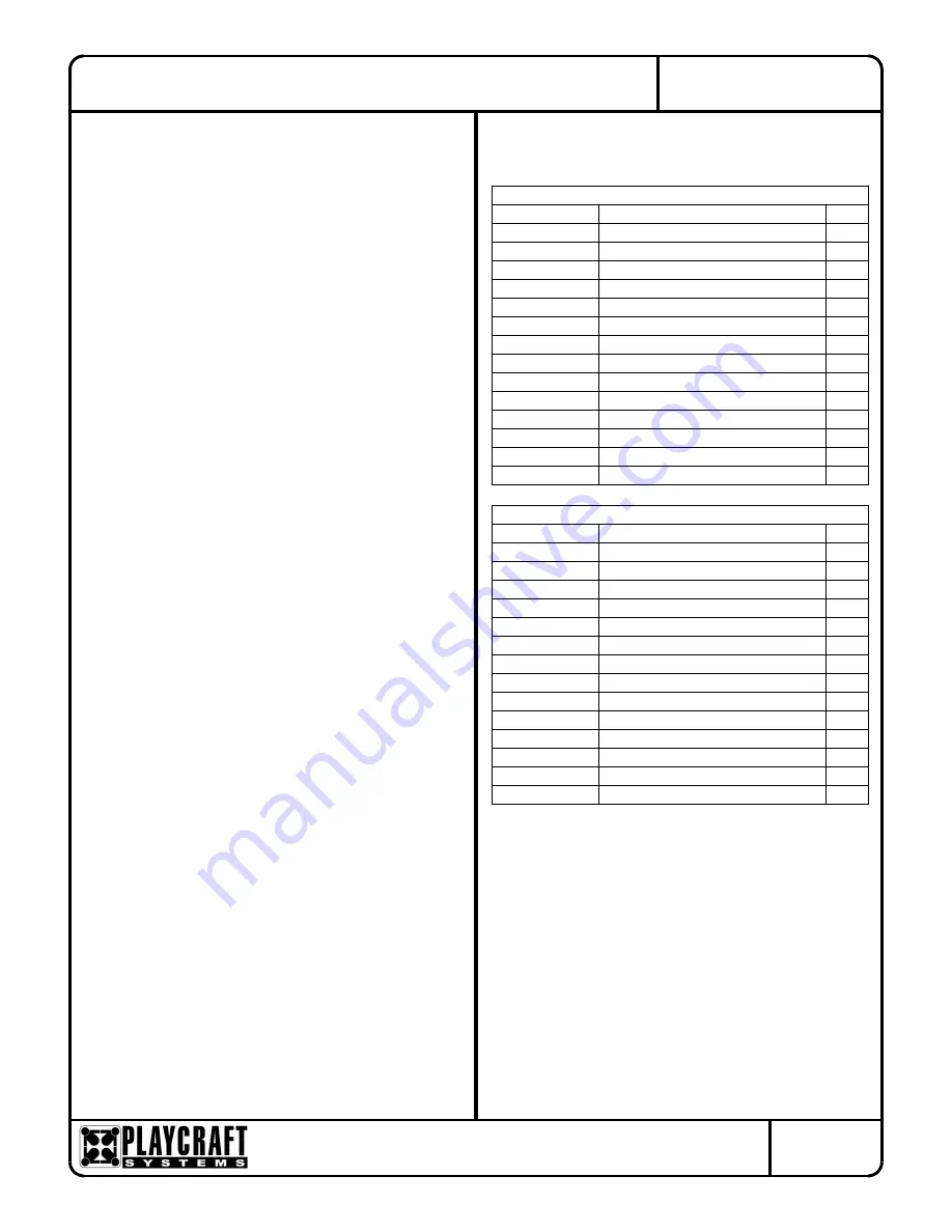
Parts List
Flat Ramp w/ Walls
Part #
DESCRIPTION
QTY.
CF-7126
Ramp R5
2
FS-1208-LEGFLT
Flat Ramp Leg R5
2
FS-1208-RWLFLAT
Flat Ramp Wall Set 12' R5
1
GF-7006-B
Mounting Block R5 Bottom
8
GF-7006-T
Mounting Block R5 Top
8
9103062-TR
Bolt Button Head 3/8" x 1-1/4"
24
9103072-TR
Bolt Button Head 3/8" x 1-1/2"
2
9103112-TR
Bolt Button Head 3/8" x 2-1/2"
4
9143112-TR
Bolt Shoulder 3/8" x 2-1/2" BH
4
9281062-5-TR
Screw Soc HD CS 1/4" x 1-3/8" TR
4
9333002
Washer Flat 3/8" x 1" O.D. x .100" thick
56
9345002
Washer Flat SAE 1/2"
12
9413002
Nut Lock 3/8"
26
9443092-TR
Nut Barrel 3/8" x 2" BH
8
Flat Ramp w/ Rails
Part #
DESCRIPTION
QTY.
CF-7126
Ramp R5
2
FS-1208-LEGFLT
Flat Ramp Leg R5
2
FS-1208-RRAFLAT
Flat Ramp Rail Set 12' R5
1
GF-7006-B
Mounting Block R5 Bottom
8
GF-7006-T
Mounting Block R5 Top
8
9103062-TR
Bolt Button Head 3/8" x 1-1/4"
24
9103072-TR
Bolt Button Head 3/8" x 1-1/2"
2
9103112-TR
Bolt Button Head 3/8" x 2-1/2"
4
9143112-TR
Bolt Shoulder 3/8" x 2-1/2" BH
4
9281062-5-TR
Screw Soc HD CS 1/4" x 1-3/8" TR
4
9333002
Washer Flat 3/8" x 1" O.D. x .100" thick
56
9345002
Washer Flat SAE 1/2"
12
9413002
Nut Lock 3/8"
26
9443092-TR
Nut Barrel 3/8" x 2" BH
8
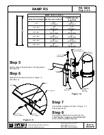
Step 9
Plumb and level entire component. Pour
concrete into footing hole. Allow at least 72
hours to cure before using this equipment. (See
Note B)
Step 10
Place appropriate compliant protective surfacing
under and around Ramp. (See Note D)


