background image


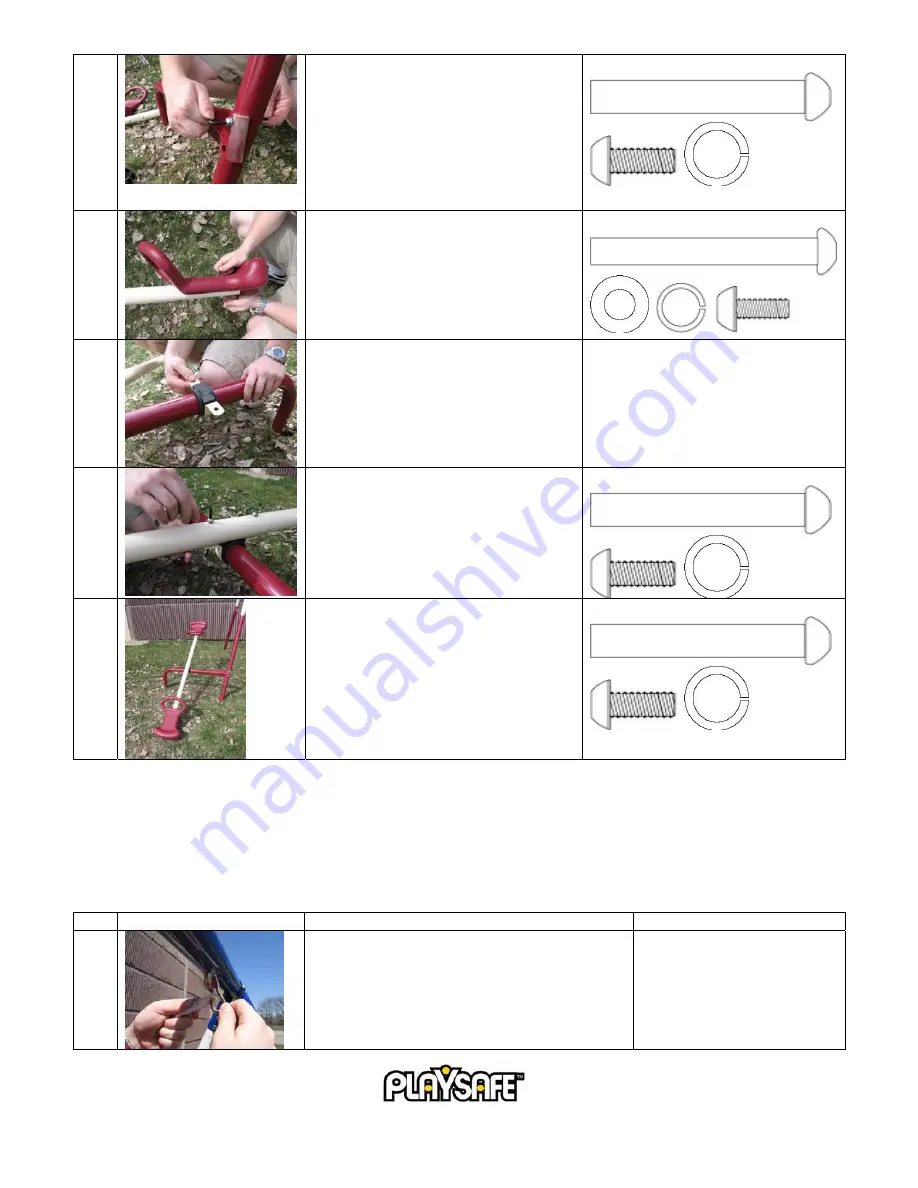
Secure the frame attachment to the leg of 
the frame with the hardware provided on 
the leg.  

NOTE:

  Be sure that the see-saw frame 

attaches to the leg on the opposite side of 
the slide.  If the leg with the holes is near 
the support bar with the slide attachments, 
it should be moved to the other end. 
 

Part Ref. #:  PSHW10  


Install the seats on the see-saw bar.  Check 
the nuts and bolts on the seat so that they 
are secure. 
 

Part Ref. #:  PSHW16 


Mount the pivot onto the frame 
attachment.  The pivot should be between 
the two screw heads, starting with the 
plastic bushing and then the metal bracket.  


Attach the see-saw bar to the pivot using 
the hardware found on the see-saw bar.   
 

Part Ref. #:  PSHW10 


Once fully assembled, check that the see-
saw hinges freely.  If it does not, make 
sure that the bolts on the see-saw bar are 
not overly tightened.   
 

Part Ref. #:  PSHW10 


SWING AND TRAPEZE ASSEMBLY 


Pre-Assembled Parts 


Swing seats should be attached to the chain. 


Step Illustration 

Instructions 

Hardware 

Reference 


Hang the swings and trapeze in place from the 
swing hooks. 


10 


©

2006 Pacific Cycle, Inc.


Summary of Contents for 22-PS300S

Page 1: ...NY OTHER WARRANTY ANY IMPLIED WARRANTIES INCLUDING ANY WARRANTY OF MERCHANTABILITY AND WARRANTY OF FITNESS FOR A PARTICULAR PURPOSE IS LIMITED IN DURATION TO THE DURATION OF THIS EXPRESS WARRANTY This limited warranty gives you specific legal rights and you may also have other rights which may vary from state to state This warranty is extended only to the original consumer purchaser for non commer...

Page 2: ...URFACE A FALL ONTO A HARD SURFACE CAN RESULT IN SERIOUS INJURY OR DEATH TO THE USER ONLY ADULTS SHOULD ASSEMBLE OR DISASSEMBLE THIS SWING SET THIS PRODUCT MUST BE ANCHORED ANCHORS ARE SOLD SEPARATELY CALL 1 800 242 6110 OR EMAIL INFO PLAYSAFEOUTDOORS COM ADULT SUPERVISION OF CHILDREN IS REQUIRED AT ALL TIMES WHEN ON OR AROUND THIS SWING SET NEVER LEAVE CHILDREN UNATTENDED DO NOT SWING TOO HIGH OR ...

Page 3: ...Playsafe recommends anchoring the swing set in concrete especially in soft or sandy soil When this is not possible anchors can be purchased by calling 1 800 242 6110 To anchor the swing set in concrete dig a hole at least 5 deep and 10 to 12 in diameter Place the swing set leg in the hole preferably on a brick or stone to keep if from sinking Be sure the swing leg is set 3 below the ground Also ma...

Page 4: ...e playground equipment the availability of material in your area and its cost The information above has been extracted from CPSC documents Playground Surfacing technical Information guide and Handbook for public Playground Safety Copies of these documents can be obtained by sending a postcard to the Office of Public Affairs USCPSC Washington D C 20207 or by calling 1 800 638 2772 CARE AND MAINTENA...

Page 5: ...ng 5 2006 Pacific Cycle Inc Name Each Vertical Tubes 4 Seat Backrest 4 Foot Plate 2 Arm Rest 2 Seat Support Bar 8 Foot Plate Support Bar 2 Glider Name Each Glider Pole vertical with Foot Rests 2 Glider Pole horizontal with Seats 2 Glider Frame Attachment 1 Swings and Trapeze Name Each Swing Seat with Chains 2 Trapeze 1 Slide Name Each Rail Ladder Leg 2 Front Leg 1 Slide 1 Ladder Step 2 PRE ASSEMBL...

Page 6: ...Hardware Reference 1 Join the two sections of the top bar together by connecting the center frame fitting with the hardware that is already placed in the top bar Part Ref PSHW10 2 Remove the hardware from the center prong of the corner fitting and insert the top bar Once the holes are aligned re insert the hardware Part Ref PSHW10 3 Repeat the process for the opposite corner fitting Then turn the ...

Page 7: ...port bar and re insert the hardware through both Repeat the process for the opposite side and center legs It may be necessary to pull both legs towards each other in order for the holes to align properly NOTE One support bar has holes for the slide attachment The holes should be positioned toward the front of the swing set Part Ref PSHW12 GLIDER ASSEMBLY Required Parts Vertical Poles x2 Footrests ...

Page 8: ...l bar with the glider attachment and re insert the hardware Repeat the process for the other side NOTE The curved portion of the pole is the top and it should face the inside of the swing frame Part Ref PSHW21 PSHW36 3 Connect the two horizontal poles must first be disassembled from the seats to the two vertical poles using the hardware provided Be sure that the plastic bushings are between the ve...

Page 9: ...EMBLY Required Parts See Saw Bar and Extension Frame Attachment Support Attachment Seat x2 Step Illustration Instructions Hardware Reference 1 Remove the hardware from the frame attachment and connect the extension Re insert the hardware and tighten NOTE Be sure that the lower part of the see saw extension is buried and anchored per the anchoring instructions on page 3 Part Ref PSHW10 9 2006 Pacif...

Page 10: ...unt the pivot onto the frame attachment The pivot should be between the two screw heads starting with the plastic bushing and then the metal bracket 5 Attach the see saw bar to the pivot using the hardware found on the see saw bar Part Ref PSHW10 6 Once fully assembled check that the see saw hinges freely If it does not make sure that the bolts on the see saw bar are not overly tightened Part Ref ...

Page 11: ...4 Foot Plate x2 U Shaped Hand Rail x4 Seat Support Bar x8 Seat Backrest x4 Assembly drawing Completed Swing Step Illustration Instructions Hardware Reference 1 Secure the lawn swing attachments with the V screws and the bolts at the squared portions of the top bar NOTE This is the same as Step 1 in the Glider Assembly section Part Ref PSHW35 PSHW22 11 2006 Pacific Cycle Inc ...

Page 12: ... Ref PSHW21 PSHW36 3 Join the two footrest sections by twisting them together until the Playsafe logo aligns 4 Insert the foot plate support bar through the footrest 5 Using an adjustable wrench attach the vertical poles to the foot plate support bar Repeat steps 5 and 6 for the other side of the footrest Part Ref PSHW4 6 Attach the four U shaped hand rails to the vertical poles NOTE The U shaped ...

Page 13: ...h the seat support bars and backrests NOTE This step is identical to Step 8 for installing the seats Part Ref PSHW17 10 After fully assembled ensure the lawn swing swings freely If it does not make sure that the bolts holding the vertical poles to the top bar attachment are not overly tightened Part Ref PSHW21 PSHW36 SLIDE ASSEMBLY Required Parts Slide x1 Rail Ladder Leg x2 Front Leg x1 Ladder Ste...

Page 14: ...from the holes in the slide Part Ref PSHW24 2 Insert the rail ladder legs through the holes in the top of the slide Align the ladder holes with the slide holes 3 Insert the screws through the holes in the back of the slide and secure them to the hand rails with the screws and locking nuts provided Part Ref PSHW24 4 Locate the slide front leg and insert it into the front outside hand rail tube on t...

Page 15: ... PSHW17 TIP In order to keep the slide legs from sinking into the ground place a flat rock or a brick under the legs You should dig out a place for the brick so the slide remains even IMPORTANT LAST STEPS TIGHTEN ALL HARDWARE Do not allow children to play on the swing set until it is fully assembled all items are tightened and the unit is properly anchored Do not over tighten nuts and bolts Once t...

Reviews: