background image


©

2006 Pacific Cycle, Inc.


Remove the hardware from the middle 
section of a leg.  Match up the holes of the 
mid-leg and support bar and re-insert the 
hardware through both.  Repeat the process 
for the opposite side and center legs.  It 
may be necessary to pull both legs towards 
each other in order for the holes to align 
properly. 

NOTE:

  One support bar has holes for the 

slide attachment.  The holes should be 
positioned toward the front of the swing set 
and opposite of the leg that has two bolts 
near the bottom of the leg. 

Part Ref. #:  PSHW12 


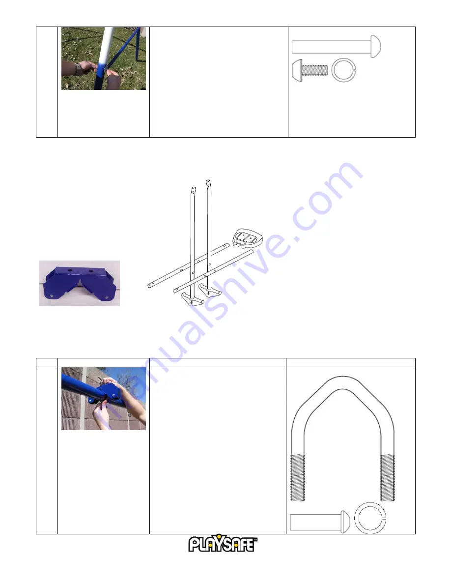
GLIDER ASSEMBLY 


Required 

Parts: 

     Vertical 

Poles 

x2 

(Footrests 

attached) 


Glider attachment  x1 


Horizontal Poles x2 (Seats attached) 

 
Pre-Assembled Parts: 


The seats should be attached to the horizontal poles.  These must be disassembled to complete the steps below. 


The foot rests should be attached to the vertical poles. 


Step Illustration 

Instructions Hardware 

Reference 


Secure the glider attachment with the V-
screw and the bolts at the squared portion 
of the top bar. 
 

Part Ref. #:  PSHW35, PSHW22  


Summary of Contents for Bristol 22-PS150

Page 1: ...LY IN LIEU OF ANY OTHER WARRANTY ANY IMPLIED WARRANTIES INCLUDING ANY WARRANTY OF MERCHANTABILITY AND WARRANTY OF FITNESS FOR A PARTICULAR PURPOSE IS LIMITED IN DURATION TO THE DURATION OF THIS EXPRES...

Page 2: ...shipped postpaid to Pacific Cycle Inc Customer Service and Assistance 1 800 242 6110 Monday Friday 8am 5pm CST Please contact the Playsafe customer service team if you have any questions about our pr...

Page 3: ...THE STRENGTH AND SKILLS TO ENJOY ALL THE RIDES SAFELY BEFORE USE ON THEIR OWN DO NOT ALLOW CHILDREN TO WALK CLOSE TO BEHIND OR IN FRONT OF MOVING ITEMS DO NOT ALLOW CHILDREN TO TWIST SWING CHAINS OR L...

Page 4: ...be fatal particularly when the injury is to the head The surface under and around the playground equipment can be a major factor in determining the injury causing potential of a fall It is self eviden...

Page 5: ...epaint with a non lead based paint meeting the requirements of Title 16 CFR Part 1303 Check swing seats ropes cables and chains monthly during usage season for evidence of deterioration Replacement sh...

Page 6: ...n Swing hooks should be in place on the top bar Hardware for the legs should be in place in the corner leg fittings Hardware for the support bars should be in place on the legs Step Illustration Instr...

Page 7: ...ioned toward the front of the swing set and opposite of the leg that has two bolts near the bottom of the leg Part Ref PSHW12 GLIDER ASSEMBLY Required Parts Vertical Poles x2 Footrests attached Glider...

Page 8: ...Part Ref PSHW21 PSHW36 3 Connect the two horizontal poles must first be disassembled from the seats to the two vertical poles using the hardware provided Be sure that the plastic bushings are between...

Page 9: ...pre assembled in the top bar their position may need to be adjusted The hook assemblies shown at left will need to be positioned as shown for each ride with two chains Verify that the opening in each...

Page 10: ...f the swing set frame with the hardware provided on the leg NOTE Be sure that the see saw frame attaches to the leg on the opposite side of the slide If the leg with the holes is on the same side as t...

Page 11: ...nserting the legs into the slide The ladder steps should have screws and nuts installed These will need to be removed prior to inserting the legs and then reassembled with the head of the screw facing...

Page 12: ...to the side support bar with the corresponding holes When reassembling the hardware make sure that the lock washers on the slide railing are located on the same side as the link bar Part Ref PSHW17 T...

Reviews: