background image

customerservice@ghpgroupinc.com

11

7077-801F  •  08/20 

H. Fire Characteristics

The overall height of the flame will vary throughout the burn 

for a couple of reasons. First is that the flame will vary based 

on type of fuel or even batch of fuel. Secondly, the appliance 

adjusts  the  burn  rate  according  to  the  how  far  away  the 

room temperature is from the set temperature. This should 

not cause alarm. The third characteristic that affects the fire 

relates to general maintenance and cleaning. Infrequent or 

poor general maintenance will result is poorer performance. 

Indicators of the need for additional maintenance activities 

include  a  lazy  flame,  black  sooted  glass,  pellets  not 

igniting, or pellets falling to the side of the firepot. See the 

maintenance section for additional information.

I. Ignition Cycles

1.  At the beginning of each ignition cycle, it is normal to see 

some smoke in the firebox. The smoke will stop once the 

fire starts.

2.  The  convection  blower  will  automatically  turn  on  after 

your  appliance  has  been  burning  for  approximately 

10 minutes.

3.  This blower transfers heat from your appliance into the 

room,  and  will  continue  to  run  even  after  the  unit  has 

shutdown. It will turn off after the exhaust temperature 

has cooled.

4.  Occasionally the appliance may run out of fuel and shut 

itself down. When this happens the empty hopper alarm 

will be triggered.

J. Running in Minimum or Maximum

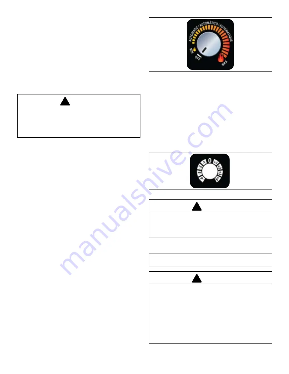
When  the  dial  control  is  set  to  run  on  the  minimum  or 

maximum setting, the appliance will continue to run without 

regard to the actual temperature in the room. The appliance 

will shut off only if the dial control is set to a different setting 

or there is an error such as an empty hopper.

When running on minimum or maximum it is important to 

follow  the  daily  cleaning  activities  especially  cleaning  the 

firepot.  Failure  to  do  so  will  reduce  the  performance  of 

the appliance.

K. Running in the Automatic Mode

When the dial control is set to run in the automatic mode the 

unit will adjust the actual burn rate based on the difference 

between  the  room  temperature  as  sensed  by  the  probe 

located in the rear of the unit and the desired comfort level 

as set on the dial control.

The comfort level range is from 65 degrees Fahrenheit to 82 

degrees Fahrenheit.

Once the desired comfort level is achieved the appliance will 

automatically shut down and turn off. When the temperature 

in  the  room  drops  3  degrees  below  the  desired  comfort 

level, the appliance will automatically restart.

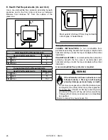
M. Clear Space

NOTICE:

  Clearances  may  only  be  reduced  by  means 

approved by the regulatory authority having jurisdiction.

Mantel:

  Avoid  placing  candles  and  other  heat-sensitive 

objects on mantel or hearth. Heat may damage these objects.

L. Trim Adjustment

Trim  adjustment  is  the  small  dial  located  below  the  main 

dial control. Rotating this dial will adjust the air/fuel ratio and 

below are examples of when to use it:

• 

If  the  fire  is  too  large,  lazy  or  producing  black  soot, 

rotate the dial counterclockwise one level at a time and 

allow 15 minutes for stabilization before making another 

adjustment

• 

If your fire is too small and sometimes goes out when 

there are pellets in the hopper, rotate the dial clockwise 

one level at a time and allow 15 minutes for stabilization 

before making another adjustment.

Odors,  vapors,  and  smoke  released  during 

initial operation.

• 

Curing of high temperature paint.

• 

Open windows for air circulation.

Odors may be irritating to sensitive individuals.

CAUTION

!

RISK OF FIRE!

Do NOT place combustible objects in front or to the sides 

of the appliance. High temperatures may ignite clothing, 

furniture or draperies.

WARNING

!

RISK OF FIRE!

Keep  combustible  materials,  gasoline  and  other 

flammable vapors and liquids clear of appliance.

• 

Do  NOT  store  flammable  materials  in  the 

appliance’s vicinity.

• 

Do NOT use gasoline, lantern fuel, kerosene, charcoal 

lighter fluid or similar liquids to start or “freshen up” a 

fire in this heater.

Keep all such liquids well away from the heater while it is 

in use as combustible materials may ignite.

WARNING

!

Summary of Contents for PH35PS-B

Page 1: ...SULT IN PROPERTY DAMAGE BODILY INJURY OR EVEN DEATH CONTACT LOCAL BUILDING OFFICIALS ABOUT RESTRICTIONS AND INSTALLATION INSPECTION REQUIREMENTS IN YOUR AREA SAVE THESE INSTRUCTIONS Questions problems missing parts Before returning to your retailer call our customer service department at 877 447 4768 8 30 a m 4 30 p m CST Monday Friday or email us at customerservice ghpgroupinc com PH35PS B PH50PS...

Page 2: ... Fire pot in the General Maintenance section of Owner s Manual under Maintaining and Servicing the Appliance NOTE If the appliance fails to ignite the LED light will blink red 4 times continuously indicating a missed ignition alarm repeat lighting steps 1 through 5 NOTE It may take up to 20 minutes for a missed ignition alarm Figure 2 1 Figure 2 2 3 3 1 1 2 2 4 Inspect hopper and ensure there is p...

Page 3: ...ing Servicing Your Appliance A Proper Shutdown Procedure 13 B Quick Reference Maintenance Chart 13 C General Maintenance 14 D High Ash Fuel Content Maintenance 17 E Frequently Asked Questions 18 5 Replacement Parts A Convection Blower Replacement 19 B Exhaust Blower Replacement 19 C Snap Disc Replacement 20 D Igniter Replacement 20 E Baffle Removal Replacement 20 F Glass Replacement 21 G Control B...

Page 4: ...e required clearances when locating the unit Refer to the label on the rear of the unit for required clearances 9 Contact your local municipal or provincial fire authority for information of how to handle a chimney fire Have a clear understood plan to handle a chimney fire In the event of a chimney fire CALLTHE FIRE DEPARTMENT 10 Prior to burning the unit for the first time make sure the hardware ...

Page 5: ... Efficiency 74 6 75 9 EPA BTU Output 6 800 to 26 000 hr 6 900 to 34 100 hr BTU Input 9 600 to 33 200 hr 9 800 to 44 400 hr Vent Size 3 or 4 inches L or PL Hopper Capacity 40 lbs 80 120 lbs Fuel Premium Wood Pellets Weighted average LHV Low Heating Value efficiency using data collected during EPA emissions tests in accordance with the requirements of CSA B415 1 Weighted average HHV High Heating Val...

Page 6: ...oom it is recommended that 3ft of vertical be installed prior to horizontally exiting the room and a smoke CO alarm be installed in the bedroom The size of the room must be at least 50ft per 1 000 Btu hr stove input if the stove exceeds the room size outside air must be installed J California PROP65 G Non Combustible Materials Material which will not ignite and burn composed of any combination of ...

Page 7: ...terial it may have a high or low ash content Higher Ash Content Material Hardwoods with a high mineral content Fuel that contains bark Standard grade pellets or high ash pellets Lower Ash Content Material Most softwoods Fuels with low mineral content Most premium grade pellets 2 2 General Information Clinkers Minerals and other non combustible materials such as sand will turn into a hard glass lik...

Page 8: ... 3 3 General Operating Information WARNING HOT SURFACES Glass and other surfaces are hot during operation AND cool down Hot glass will cause burns Do not touch glass until it is cooled NEVER allow children to touch glass Keep children away CAREFULLY SUPERVISE children in same room as appliance Alert children and adults to hazards of high temperatures High temperatures may ignite clothing or other ...

Page 9: ...t downs may be required for cleaning AUTO To burn in the Automatic mode turn the dial control clockwise to the desired comfort level When operating in the automatic mode the unit changes the burn setting based on the difference between the room temperature and the desired set point In other words the unit will burn on High if the difference between the desired and room temperature is greater than ...

Page 10: ...d will be terminated during this shutdown process The exhaust and convection blowers will remain on during the shutdown process until the exhaust has cooled If maintenance or daily cleaning is going to be conducted immediately following a shutdown please use caution as components especially those inside the firebox may still be hot Please note that if the dial control is turned to the off position...

Page 11: ...n the dial control is set to run in the automatic mode the unit will adjust the actual burn rate based on the difference between the room temperature as sensed by the probe located in the rear of the unit and the desired comfort level as set on the dial control The comfort level range is from 65 degrees Fahrenheit to 82 degrees Fahrenheit Once the desired comfort level is achieved the appliance wi...

Page 12: ...opper runs out of fuel the user changes the dial control to a different state or the unit senses an error Amber Blinks Continuously Appliance is in the in shutdown sequence During shut down the blowers will shut off when the exhaust temperature has cooled Red 1x Empty Hopper Alarm This alarm is caused by the fire going out from lack of fuel See troubleshooting section for more information Red 2x E...

Page 13: ...type OR X B Quick Reference Maintenance Chart Follow the detailed instructions found in this section for each step listed as referenced in the chart below NOTICE These are recommendations Clean more frequently if you encounter heavy build up of ash at the recommended interval or you see soot coming from the vent Not properly cleaning your appliance on a regular basis will void your warranty When p...

Page 14: ...g tool to break up deposits inside the firepot and dispose in an approved container Depending on the quality of fuel used the front of the firepot may need to be removed for better access for cleaning c Use the narrow end of the firepot cleaning tool to clean the holes d With the firepot out clean the area below the firepot e Reassemble the firepot and place back inside the firepot riser Make sure...

Page 15: ...y cool before cleaning glass b Vacuum fly ash from glass and door rope c Use a damp paper towel or any non abrasive glass cleaner Wipe off with dry towel 4 Disposal of Ashes Frequency As needed By Homeowner Ashes should be placed in a metal container with a tight fitting lid The closed container of ashes should be placed on a non combustible floor or on the ground well away from all combustible ma...

Page 16: ...t side panel c Sweep or vacuum out any build up on the impellers Use a brush or compressed air to loosen dirt if needed Avoid damaging the impellers 8 Door Handle Inspection Frequency Monthly or prior to heating season By Homeowner The gasket between the glass and firebox should be inspected periodically to make sure there is a good seal 7 Cleaning the Exhaust Path Baffles Drop Tube Frequency Mont...

Page 17: ...ash The fly ash will collect in the exhaust venting system and restrict the flow of the flue gases At start up if there is incomplete combustion or if there is a shutdown or incorrect operation of the appliance it will lead to some soot formation This will collect in the exhaust venting system The venting chimney system may need to be cleaned at least once a year or more often depending upon the q...

Page 18: ...ed in sea water These pellets can have a higher salt content and cause the metals in the unit to corrode prematurely and deteriorate If you are seeing any components inside the firebox deteriorate it is recommended to change pellet brands immediately Is there a place to lubricate the blowers to quiet them down The most often cause of noisy blowers is from the impellers becoming dirty over time See...

Page 19: ...blower back and it will release B Exhaust Blower Replacement 1 Turn the dial control to the off position Unplug the power to the unit 2 Remove the left side panel by loosening the two or three bolts in the rear of the unit 3 Disconnect 2 white wires from the white and blue wires of the exhaust blower 4 Remove the blower motor attached to a removable plate on the exhaust blower Depending on the mod...

Page 20: ... on the rear of the unit holding on the left side panel You do not need to remove the screws Remove side panels by lifting up and out 3 Locate the snap disk on the top side of the feed tube where it meets the hopper Disconnect the wire leads from the snap disk 4 Using a 1 Phillips screwdriver remove two 6 32 fasteners retaining the snap disk onto the side of the feed tube 5 Using the same fastener...

Page 21: ... connector from the feed motor 3 Using pliers remove the cotter pin 4 Remove the feed motor from the feed shaft 5 Reinstall the new feed motor by aligning the clearance hole in the feed motor shaft with the auger spring shaft 6 Plug the feed motor leads back in and restore power J Feed Spring Replacement 1 Empty the hopper of all pellets then follow the steps to remove the feed motor above 2 Remov...

Page 22: ...se weights prior to installation Add sufficient additional support to meet this weight requirement prior to installation 1 Appliance Location Installation MUST comply with local regional state and national codes and regulations Consult insurance carrier local building inspector fire officials or authorities having jurisdiction over restrictions installation inspection and permits It is a good idea...

Page 23: ...ng Thoroughly clean the exhaust path and venting See Maintenance Section Inspect for worn or broken gaskets Repair any gaskets suspected of leaking or adjust the trim Upper level air leaks such as Recessed lighting Attic hatch or open windows Duct leaks To minimize the effects of negative air pressure Install the outside air kit with the intake facing prevailing winds during the heating season Ens...

Page 24: ... 26 13 16 681 4 1 8 105 19 7 8 505 4 102 23 3 4 603 24 5 16 617 34 864 13 330 30 13 16 783 4 1 8 104 24 3 8 620 A Appliance Dimensions PH35PS B B Appliance Dimensions PH50PS B 7 7 Dimensions Clearances 3 1 2 89 21 3 4 552 21 15 16 558 ...

Page 25: ...zontal Flue Installations Straight Back Against Wall Inches Millimeters A Back Wall to Appliance 2 51 B Back Wall to Flue Pipe 3 76 C Side Wall to Appliance 13 330 C Appliance Dimensions PH50CABPS B Do NOT connect this unit to a chimney flue servicing another appliance Do NOT connect to any air distribution duct or system CAUTION WARNING HOT SURFACES Glass and other surfaces are hot during operati...

Page 26: ...r as indicated Measure front distance M from the surface of the glass door USA Hearth Pad Requirements Hearth Pad Requirements Inches K Sides 2 L Back 2 M Front 6 Canada Hearth Pad Requirements Hearth Pad Requirements Millimeters K Sides 203 L Back 51 M Front 152 Must extend 2 inches 51mm beyond each side of pipe shaded area L K M K WARNING If the information in these instructions is not followed ...

Page 27: ... building Not less than 48 inches 1 2m below Not less than 48 inches 1 2m horizontally from Not less than 12 inches 305mm above 3 Distance from permanently closed windows Not less than 12 inches 305mm below horizontally from or above 4 Distance between bottom of termination and grade should be 12 inches 305mm minimum This is conditional upon plants in the area and nature of grade surface The grade...

Page 28: ...r type L or PL vent D Pipe Selection Chart The chart will help you in determining proper venting size according to the equivalent feet of pipe calculated previously and the altitude above sea level of this installation a Locate the calculated equivalent feet of pipe on the vertical left side of the chart b Move to the right horizontally on the chart until you reach your altitude above sea level c ...

Page 29: ...ows 0 5 10 15 20 25 0 2 4 6 8 10 12 Length of Horizontal Sections ft Minimum Vertical Rise ft Minimum Vertical Vent for Three Elbows Length of Horizontal Sections FT Minimum Vertical Vent for Two Elbows 0 5 10 15 20 0 5 10 15 Length of Horizontal Sections ft Minimum Vertical Rise ft Minimum Vertical Vent for Two Elbows Length of Horizontal Sections FT Minimum Vertical Vent for One Elbow 0 5 10 15 ...

Page 30: ...nch 76mm air clearance to no less than 1 inch 25mm air clearance to combustibles for approved Listed pellet pipe Follow pipe manufactures listed air clearances to combustibles and installation instructions for all reduced air clearances installations C Vertical into Existing Class A Chimney B Through The Wall Vertical External Horizontal A Vertical Interior Typical Installation 9 9 Vent Systems PR...

Page 31: ...Fireclay flue Liner with Airspace Concrete Cap 1 in 25mm Clearance with Firestop 6 in 152mm Minimum Fire Risk Inspection of Chimney Masonry chimney must be in good condition Meets minimum standard of NFPA 211 Factory built chimney must be minimum 6 inch 152mm UL103 HT WARNING Improper installation adjustment alteration service or maintenance can cause injury or property damage Refer to the owner s...

Page 32: ...tion cap is 6 inches 152mm there is the possibly of soot build up around the termination area If this occurs we suggest to move the termination further away from the house to prevent it The suggested minimum is 12 inches DO NOT DOWNWARD VENT The following will occur The appliance will not vent properly Smoke spillage in the house Excessive sooting CAUTION 6 in 152mm Minimum Non combustible Hearth ...

Page 33: ...onoxide and different fuels generate different levels Carbon monoxide Only use approved fuels in this appliance Always keep door shut during operation Operating this appliance with doors open can allow CO to leak into the home CO can kill you before you are aware it is in your home At lower levels of exposure CO causes mild effects that are often mistaken for the flu These symptoms include headach...

Page 34: ... unit Using the hose clamp attach the flex pipe to the 2 tube welded to the rear of the firebox as shown in the photo B Power up the Unit Plug the unit into 120VAC power 11 11 Appliance Set Up Never draw outside combustion air from Wall floor or ceiling cavity Enclosed space such as an attic garage or crawl space CAUTION Shock hazard Do NOT remove grounding prong from plug Plug directly into prope...

Page 35: ...ture Exhaust path is dirty Exhaust probe is not attached to outlet Exhaust probe is not plugged in to the board Exhaust probe is defective error code may result Clean firepot Check flue vent for obstruction Inspect and clean exhaust path and venting clean firebox including behind the baffles Inspect and clean the exhaust outlet especially the right side wall Remove the right side panel and inspect...

Page 36: ...oard and failed component Igniter does not turn off Igniter short circuit The fuse will be blown and upon replacement of the fuse the igniter will remain on when unit has power Inspect wires blowers and power cord to find cause of short circuit Replace board and failed component Feed motor does not shut off Feed motor short circuit The fuse will be blown and upon replacement of the fuse the feed m...

Page 37: ...he probe into the board Replace the component 4 Flashes Missed Ignition During the ignition sequence the load does not ignite The unit will automatically retry once from the first failed attempt Fuel No fuel Hopper Empty Feed Jam Feed doesn t turn Feed motor disconnected or failed Firepot Firepot Dirty so fuel is not near ignition hole in the firepot Igniter No power Debris in the end of the ignit...

Page 38: ...els over the red hot igniter creating super heated air that ignites the pellets 10 Power Supply The power cord connector in the rear of the unit Check the wall receptacle for 120 volt 60 Hz standard current Make sure the outlet is grounded and has the correct polarity A good surge protector is recommended 13 13 Reference Materials 11 Exhaust Probe The exhaust probe is mounted to the side of the ex...

Page 39: ...OWER VACUUM SWITCH HOPPER SWITCH AMBIENT TEMPERATURE EXHAUST TEMPERATURE SERIAL PORT SERVICE ONLY BLACK WHITE PURPLE PURPLE BLUE BLUE RED RED BLACK BLACK POT SET TEMP VCC POT SET TEMP GND POT SET TEMP SIG POT FEED ADJUST VCC POT FEED ADJUST GND POT FEED ADJUTS SIG LED RED LED AMBER LED GREEN FUSE SNAP DISC B Wiring Diagram ...

Page 40: ...mm Ceramic Glass 12 5 Feed Motor Gasket 4 Baffles 3 per unit 12 6 Rubber Grommet 5 Firepot 12 7 Feed Motor 6 Convection Blower 13 Control Board 7 Igniter 14 Exhaust Probe not pictured 8 Igniter Chamber 15 Ambient Probe not pictured 9 Exhaust Blower When ordering replacement parts specify model to get the correct parts 10 Snap Disk Vacuum Switch Hopper Switch 11 Dial Control 1 2 5 4 8 6 7 10 9 3 11...

Page 41: ...customerservice ghpgroupinc com 41 7077 801F 08 20 D Service Maintenance Log Date of Service Performed By Description of Service ...

Page 42: ...ical systems such as furnaces clothes dryers fans etc 11 This warranty is void if The appliance has been operated in atmospheres contaminated by chlorine fluorine or other damaging chemicals This appliance has been subjected to prolonged periods of dampness or condensation The appliance has any damage due to water or weather damage that is the result of but not limited to improper chimney venting ...

Page 43: ...customerservice ghpgroupinc com 43 7077 801F 08 20 ...

Page 44: ...GHP Group with any questions or concerns www ghpgroupinc com For Customer Service 1 877 447 4768 Prior to calling please have the model serial number and sales receipt of the unit you are calling about This information can be found at the rear of the unit CONTACT INFORMATION Manufactured for GHP at ClearWater Metals Lot CN2 Mai Trung IZ Ben Cat Town Binh Duong Providence Vietnam Made in Vietnam 64...

Reviews: