background image

18

FRESH WATER SYSTEMS

The water system built into your motorhome provides full service 

similar to the system in your home.  A 12-Volt self-priming pump 

draws pressurized water from the fresh water tank to all cold 

faucets and the water heater.  An automatic pressure switch 

located in the water pump maintains a positive line pressure 

between 20 to 30 psi.  The fresh water tank is in a compartment 

below the raised floor in the rear of the coach, this is a heated 

compartment. The gray water tanks are located in the cabinet next 

to the sink, these are portable water tanks.  The portable black 

water tank is part of the cassette toilet and it can be accessed 

through the toilet door on the outside of the coach.

FURNACE

Please refer to the manufacturer’s operating instructions for further information. 

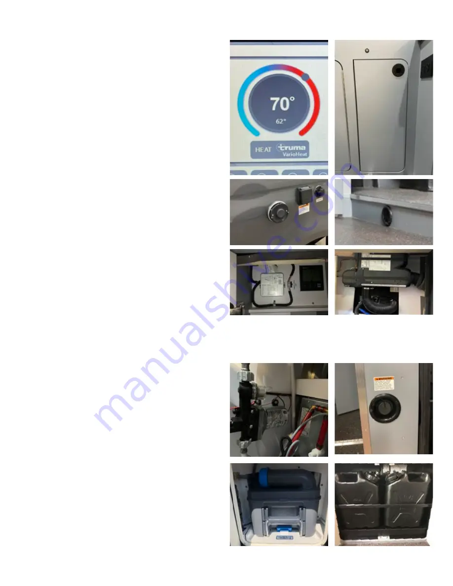
Your vehicle is equipped with a Truma VarioHeat 11,500 BTU 

furnace. It is a LP gas and 12 volt appliance. The furnace is 

located under the driver side cabinet behind the grey tanks. To 

access the the furnace, remove the grey water tanks and the cover 

panel behind the grey tanks. The thermostat is controlled by the 

touchscreen control panel.  

1.  Ensure that there is propane supplied to the coach.
2.  Ensure there is 12V power to the coach.
3.  Turn on the Truma control from the icon on the touchscreen, 

adjust the temperature by moving the dot around the scale.

4.  When you start the furnace, the furnace fan will run to clear 

the system, then the flame will ignite and start the heating 

process. The furnace will maintain the desired temperature.  

(see Truma VarioHeat manual for setting information)

5.  If the furnace fails to ignite the first time you turn it on it 

will try to ignite another three times . If the furnace does 

not ignite, it will go into lock out mode.  Wait five minutes 

then turn off  the battery switch and turn it back on. This will 

reset the furnace, turn the furnace on at the touchscreen 

and set the temperature.

6.  The furnace has a communication module, a 2amp fuse and 

the CP plus control located in the small cabinet next to the 

sink. The CP communicates with the touchscreen through 

the bridge module. The CP plus panel will show faults and 

give you a code for troubleshooting.

Summary of Contents for 2022 REKON 4X4

Page 1: ...A 2022 REKON 4X4 Mercedes Benz Sprinter 2500 4x4 OWNER S MANUAL...

Page 2: ...OR SERIOUS INJURY Overfilling the propane container can result in uncontrolled propane flow which can cause fire or explosion A properly filled container contains approximately 80 percent of its volu...

Page 3: ...l be glad to answer any further questions about the operation of your motorhome and the appliances All reasonable precautions have been taken in the preparation of this manual We have been as accurate...

Page 4: ...ower 08 Water Heater Vent Access Door 09 Waste Tank Compartment 09 Grey Water Connections 09 Furnace Vent 10 120 Volt 30 Amp Power 10 City Water Connection 10 LP Compartment 11 Fresh Water Fill and Ve...

Page 5: ...Disconnect 32 Coach Batteries 34 Real Time Clock Fuse 35 Solar Panel Fuses 35 DC Load Center G12 37 DCD Panel 37 Fiamma Awning Control Center 37 Water Heater Furnace Bridge Module 38 TOUCHSCREEN CONT...

Page 6: ...F...

Page 7: ...ted Warranty as well as all other applicable warranties including but not limited to the warranty for the chassis tires batteries microwave television awning refrigerator stove fan toilet air conditio...

Page 8: ...motorhome components only if Pleasure Way deems it absolutely necessary to perform chassis warranty repairs Pleasure Way will not reimburse any costs in the removal and re installation of these compon...

Page 9: ...DITIONS OF MERCHANTABILITY FITNESS FOR A PARTICULAR OR NORMAL PURPOSE QUALITY DURABILITY AND AGAINST LATENT DEFECTS ARE HEREBY DISCLAIMED TO THE EXTENT IMPLIED WARRANTIES ARE NOT PERMITTED TO BE DISCL...

Page 10: ...or its components improper untimely or inadequate maintenance or service of the Motorhome and its components failure to follow instructions or maintenance outlined in the manuals supplied with the Mo...

Page 11: ...l loss including loss of wages or profits cost of rental vehicle cost of accommodations travel expenses including taxi bus air fares towing fuel meals telephone internet and any and all other miscella...

Page 12: ...Warranty For TWO 2 YEARS or 24 000 miles or 40 000 kilometers whichever comes first by the original retail purchaser from an authorized Pleasure Way dealer Ultraleather fabrics Propane lines Foam use...

Page 13: ...least once a year All Pleasure Way Motorhomes in Canada are CSA through QAI and CMVSS certified and may exceed the approved installation criteria All Pleasure Way Motorhomes in the United States are F...

Page 14: ...nufacturer s instructions Do not block air circulation in the area where the detector is located FIRE EXTINGUISHER A 3 pound capacity fire extinguisher is provided and located at the side door main en...

Page 15: ...or other flammable liquids inside your vehicle WARNING Ensure the propane system valve is turned off when the vehicle is in motion It is not safe to travel while propane appliances are in use The prop...

Page 16: ...atches Your choices of escape routes are as follows the main entrance at the side door the driver and passenger side front doors and the rear doors TRUMA PORTABLE FRIDGE Ensure the locking straps for...

Page 17: ...Sprinter limitations as listed in the Mercedes Benz Sprinter manual The hitch tongue weight must be included in the loaded weight of the vehicle Length Bumper to Bumper 235 19 7 594 cm Overall Height...

Page 18: ...nal Due to Pleasure Way s policy of continuous improvement Pleasure Way Industries Ltd reserves the right to make product changes at any time without incurring obligation The chassis manufacturer may...

Page 19: ...for more information see page 16 EXTERIOR 120 VOLT PLUG Located on the passenger side panel behind the rear wheel this plug will only function if power is supplied through the inverter or shore power...

Page 20: ...g is located on the passenger side of the roof this is a 10 6 Fiamma electric awning controlled by the switches located on the rear touchscreen control panel The 12 volt battery disconnect switch must...

Page 21: ...s side lower mid body Connect the Y connection in the blue bag to each of these ports and terminate the Y connection onto one of the portable grey water tanks The portable grey water tanks are stored...

Page 22: ...ing up to a shore power source that a surge protector should be used to protect the electrical system of the coach CITY WATER CONNECTION The Rekon is equipped with a city water connection located mid...

Page 23: ...e the vehicle allowing the water to slosh in the tank Drain and flush the tank with fresh potable water NOTE It is recommended that you use a water filter when filling this tank unless you use a known...

Page 24: ...n see page 46 SOLAR PANELS Your vehicle is equipped with 400W Carmanah solar panels that charge the battery bank through the GP RV 30 MPPT solar controller The charge controller is mounted in the cent...

Page 25: ...park the vehicle on a level surface Damage to the motorhome as a result of incorrect parking will not be covered under warranty When storing your Pleasure Way motorhome ensure all holding tanks are em...

Page 26: ...n set the refrigerator to operate in DC mode Use of any other appliance is not recommended while the motorhome is in motion Always wear your seat belt when the vehicle is in motion Only forward facing...

Page 27: ...operly filled container will contain approximately 80 of its volume of LP gas WARNING Do not bring or store LP gas containers gasoline or other flammable liquids inside the vehicle as a fire or explos...

Page 28: ...is set up for a low pressure LP source BASIC OPERATION 1 Ensure the black valve is in the OFF position 2 Remove the yellow cap and ensure the opening is clean 3 Pull the sleeve of quick connect back a...

Page 29: ...is turned on by the touch screen control panel 4 Turn on the water heater switch on the touchscreen control panel 5 Start the water flow on hot at a medium flow and adjust to the desired temperature...

Page 30: ...e the furnace remove the grey water tanks and the cover panel behind the grey tanks The thermostat is controlled by the touchscreen control panel 1 Ensure that there is propane supplied to the coach 2...

Page 31: ...ecommended that you use a water filter when filling this tank unless you use a known good water source FRESH WATER TANK DRAIN The fresh water tank drain is located below the coach on the driver side s...

Page 32: ...e water source on to medium pressure 4 Check for leaks at the city water connection as you may have to re tighten this connection 5 To disconnect the city water system first turn off the water source...

Page 33: ...ps as necessary the inline flow filter is clean If the water pressure drops ensure that the faucet aerators are clean there is water in the holding tank the battery is not run down the faucets and con...

Page 34: ...70 counterclockwise WASTE HOLDING TANK Please refer to the manufacturer s operating instructions for further information The waste holding tank is located on the driver side mid body exterior The hold...

Page 35: ...ank from the cassette toilet Dump and flush the waste holding black water tank Re install the tank back into the cassette toilet see the Thetford user manual for instructions 4 Open the sink lower cab...

Page 36: ...water heater These instructions can be found on page 17 21 of the Truma water heater manual 8 Remove the water line from the inlet side of the water pump this is the white braided line going into the...

Page 37: ...e cassette from the toilet step 3 and dump any residual water and antifreeze that may have accumulated during winterizing Reinstall back into the toilet again for storage 11 Open the low point drain v...

Page 38: ...anel to access this connection It is recommended that you start and run your vehicle for a short period of time each month It is recommended that the fridge freezer door be left slightly open to allow...

Page 39: ...om XC Inverter Charger The charging portion of the Freedom XC is set to LFP to charge the lithium ion phosphate batteries The Freedom XC also converts 110 volt into 12 volt to charge the batteries for...

Page 40: ...fridge The charging portion of the Freedom XC is set to LFP to charge the lithium ion phosphate batteries The Freedom XC also converts 110 volt into 12 volt to charge the batteries to operate 12 volt...

Page 41: ...r code displayed on the LCD screen For a list of error codes see Warning Messages on page 64 flashing red Indicates a Warning condition and is accompanied by an error code and a sounding alarm For a l...

Page 42: ...that houses the breakers for the 110 120 volt system The distribution panel is located below the inverter The breakers act like a household breaker make sure the breaker is shut all the way off before...

Page 43: ...cabinet The DC DC charger takes 12 volt charge from the alternator and converts it to optimal charging for the coach batteries The DC DC charger has a 2 amp trigger fuse located on the left hand side...

Page 44: ...unning The inverter for the coach will not charge the chassis battery CHASSIS BATTERY DISCONNECT This disconnect is located next to the gas pedal in the driver cabin To disconnect the chassis battery...

Page 45: ...Input Inverter Breaker Touchscreen Control Panel MASTERVOLT DC DC CHARGER CHARGING The Freedom XC inverter charger and the Mastervolt DC DC charger have been programmed to charge the coach batteries T...

Page 46: ...his type of lithium battery Any replacement lithium batteries must have High Low voltage protection Short circuit protection Over current protection and High temperature protection You must not replac...

Page 47: ...wiring out of the opening You will find two 30 amp fuses at this location REAR SOLAR PANEL 10 AMP There is also a 10 amp fuse for the rear solar panel located under the rear pot light on the driver s...

Page 48: ...C 50 A Source Voltage Must Not Exceed 18V Operating Voltage Range 10 V 14 5 V Torque Specs Min Max Fastener 60 in lb 70 in lb J6 12v Stud 30 in lb 33 in lb J7 GND Stud J3 1 21 LC 2 6A Living Room Lig...

Page 49: ...cation box furnace 2 amp fuse and the CP Plus are located in the small cabinet door next to the sink cabinet This bridge module allows the water heater and furnace to communicate with the G12 panel an...

Page 50: ...MECHANICAL and SETTINGS CLIMATE CONTROL CENTER The CLIMATE CONTROL CENTER displays the inside temperature and the desired temperature in the center circle FURNACE MODE To turn ON your Truma VarioHeat...

Page 51: ...ght button to turn ON or OFF lighting associated with the area Buttons will display in light blue when activated Buttons with UP DOWN arrows are capable of dimming Touch and hold the light button for...

Page 52: ...ge is going into the battery bank than is being used A negative number means the battery bank is being drawn down ESTIMATION GAUGE The ESTIMATION GAUGE gives an estimate of time remaining for the DC p...

Page 53: ...an The REAR fan is locationed above the murphy bed workstation and is the EXHAUST fan used to draw air out of the coach The FRONT fan is located in the galley area and is the INTAKE fan used to draw a...

Page 54: ...o change the hour reading on the display Select the right side UP DOWN arrows to change the minutes To change from AM to PM you must run the clock through the 12 hour cycle You can also adjust for a 1...

Page 55: ...MODULE The DCM3 is part of the battery shunt system and is located above the battery box The DCM3 monitors the battery status and communicates it to the G12 MODULE The SOLAR CONTROLLER communicates w...

Page 56: ...k This screen will give you an accurate account of what the battery status is the amount of discharge and the number of cycles that the batteries have had FAULTS The FAULTS display will display a syst...

Page 57: ...ook top can be placed on the sink cover for operation and plugged into the plug to the left hand side of the sink This plug is GFCI controlled by the GFCI on the outside of the entrance cabinet FRIDGE...

Page 58: ...to start the fan NOTE The fan is equipped with a rain sensor so the fan cannot be operated when it is raining The fan cannot be operated when the fan lid is closed for more information see page 41 NO...

Page 59: ...ure your solar panels are not active when servicing the batteries it is advised to cover the solar panels CAUTION Turn OFF the charge line disconnect if the vehicle is going to be in storage for a per...

Page 60: ...king handles are locked in place while the table is in use 6 This location will allow you to swivel your front seats and have a dining or work area WARNING Ensure Lagun table latched in the storage po...

Page 61: ...mbers into the retaining holes post down at the front and rear of the passenger and driver side cabinets 4 Release the yellow safety strap from the driver and passenger side Murphy beds and fold them...

Page 62: ...should be in line with the front edge of the bed the rear locking catch should be at the rear most position 7 Attach the shorter cable green tape to the front tabletop support loop and the front side...

Page 63: ...tools are provided by Mercedes Benz Please refer to the Mercedes Benz owner s manual for jacking locations NOTE The Spare tire is located under the vehicle between the hitch rails For instructions see...

Page 64: ...ntioned above to avoid flat tires and other types of tire failure you should maintain proper tire pressure observe tire and vehicle load limits avoid road hazards and regularly inspect your tires FIND...

Page 65: ...re valve stem with the edge of your tire gauge until you get to the correct pressure 4 If the tire pressure is too low note the difference between the measured tire pressure and the correct tire press...

Page 66: ...rtification and in case of a recall UNIFORM TIRE QUALITY GRADING SYSTEM UTQGS To help consumers compare a passenger car tire s treadwear rate traction performance and temperature resistance the federa...

Page 67: ...me mud and snow capability SPEED RATING The speed rating denotes the speed at which a tire is designed to be driven for extended periods of time The ratings range from 99 miles per hour mph to 186 mph...

Page 68: ...combination can cause heat build up and possible tire failure From highest to lowest a tire s resistance to heat is graded as A B or C Tires for light trucks have other markings besides those found on...

Page 69: ...has a defect which could cause a crash or could cause you injury or death you should contact Pleasure Way immediately PLEASURE WAY CONTACT INFORMATION To contact Pleasure Way you may call us toll fre...

Page 70: ...58 MAINTENANCE LOG MODEL YEAR VIN DATE PURCHASED DATE WORK PERFORMED BY MILEAGE NOTES...

Page 71: ...59 DATE WORK PERFORMED BY MILEAGE NOTES...

Page 72: ...60 302 PORTAGE AVENUE SASKATOON SK CANADA S7J 4C6 TEL 800 364 0189 FAX 306 934 7085 WWW PLEASUREWAY COM...

Reviews: