background image

25

Technical manual – Installation instructions and start-up  X-RAY R - ver. 1.0 del 07/11/2018

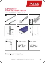
NB:

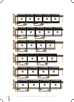
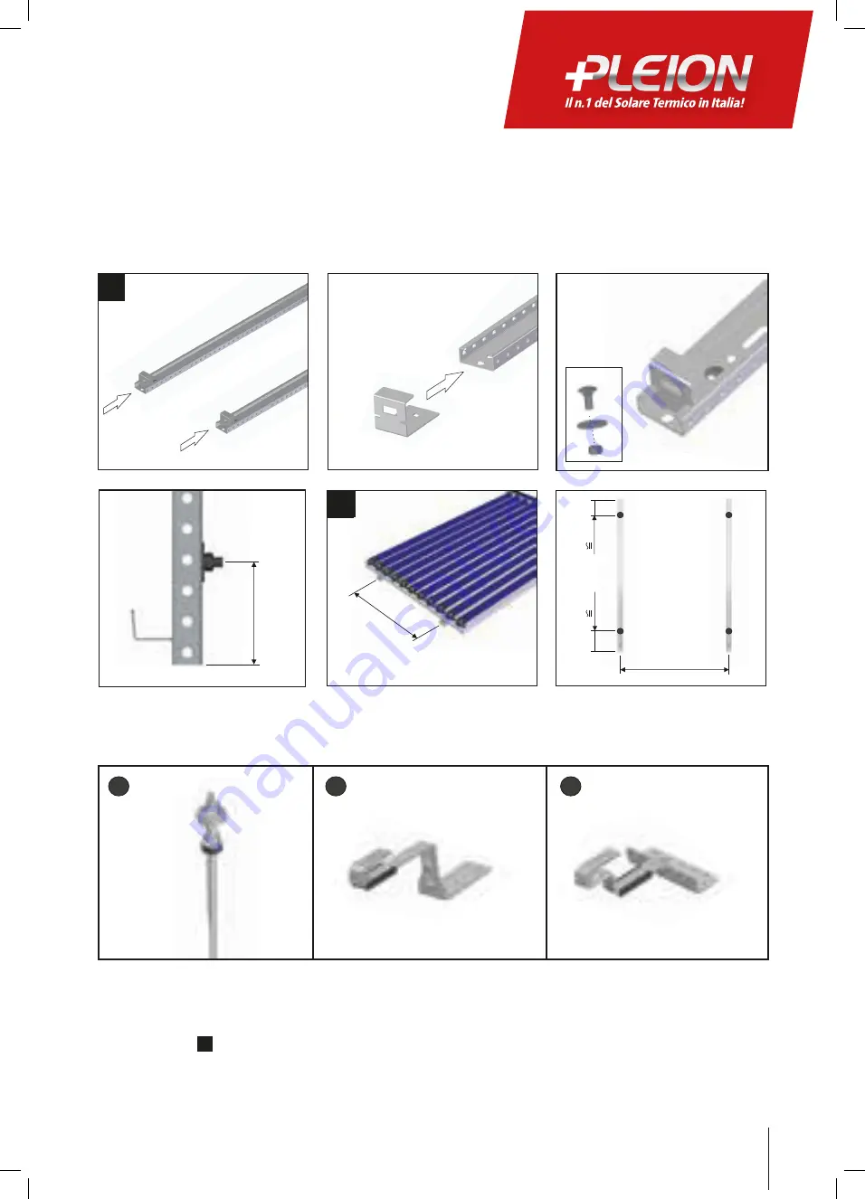
 For distance between anchorage points see page 27.

On completion of 


4


point proceed with instructions on page 31.

SLOPING ROOF

SCREW FASTENING SYSTEM

cod. 12345678

cod. 12345678

cod. 12345678

cod. 12345678

cod. 12345678

M8x20

M8x25

M8x75

M8x75

1970

1970

M8x45

M8x25

M8x30

x2

x2

x2

x2

x2

M8x20

M8x25

1970

x1

x1

x1

x1

x1

x1

x1

x1

x2

x2

x4

x2

x4

x2

1

85

M8x20

x

300

300

x

2

1

85

M8x20

x

300

300

x

2

85

M8x20

x

300

300

x

2

2

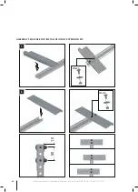
ASSEMBLY SEQUENCE FOR INSTALLATION OF BASE KIT:

TYPES OF ANCHORAGE

85

M8x20

x

300

300

x

2

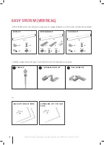
KIT VITE

KIT GANCIO DOPPIO

KIT GANCIO TEGOLA

KIT TUBO

KIT GANCIO DOPPIO

KIT GANCIO TEGOLA

SCREW KIT

SHINGLES HOOK KIT

TILES HOOK KIT

Summary of Contents for X-RAY R 10 R

Page 1: ...TECHNICAL MANUAL INSTALLATION INSTRUCTIONS AND START UP SOLAR VACUUM COLLECTORS NEW RANGE www pleion it 100 MADE IN PLEION EN...

Page 2: ...2 Technical manual Installation instructions and start up X RAY R ver 1 0 del 07 11 2018...

Page 3: ...RACK SYSTEM 13 FLAT ROOF TRACK SYSTEM 14 DISTANCE BETWEEN ANCHORAGE POINTS 20 COMPLETING BRACKET SYSTEM 23 EASY SYSTEM VERTICAL 24 SLOPING ROOF VERTICAL 25 DISTANCE BETWEEN ANCHORAGE POINTS VERTICAL 2...

Page 4: ...and straps fall arresters reope shorteners that havev been approved by authorised testing authorities Work in the vicinity of live electrical cables and wiring where contact is possible can only be ca...

Page 5: ...USE TO COVER THE SOLAR PANEL AND TO PROTECT AGAINST SUNLIGHT Remove only after the system has started functioning A Cut the cover along the dotted line and fold upwards B Place on top of the installe...

Page 6: ...THE BUILDING In accordance with the lightning protection standard VE NORM EN 62305 Part 1 4 the collector array cannot be connected to the building s lightning protection A safety distance of at leas...

Page 7: ...emperature resistant up to 250 C OPERATING PRESSURE The normal operating pressure is 2 3 bar The maximum test pressure is 10 bar START UP SOLAR LIQUID FAST G28 Premixed solar liquid ready for use in s...

Page 8: ...e panel head profile It is obligatory to use certified karabiners spring catches and ropes that have a breakage point above 2000 kg Non sollevare il collettore utilizzando gli attacchi idraulici filet...

Page 9: ...upper part of the panels The input tubes branch into heat absorption units these are U shaped copper ducts provided with heat deflectors in sheet aluminium which transfer the heat from the glass tubes...

Page 10: ...60 0 60 0 60 0 61 5 61 5 Tramittance coefficient a1 W m K 0 910 0 910 0 910 0 910 0 850 0 850 Tramittance coefficient a2 W m K 0 013 0 013 0 013 0 013 0 009 0 009 Absorber coefficient 92 92 92 92 92 9...

Page 11: ...Tramittance coefficient a2 W m K 0 009 0 009 0 009 0 009 0 009 0 005 Absorber coefficient 92 92 92 92 92 92 Emission coefficient 6 5 6 5 6 5 6 5 6 5 6 5 Coefficinet transfer of the glass 92 92 92 92 9...

Page 12: ...Completing bracket system EASY SYSTEM VERTICAL NB valid for all sizes between X RAY 10 R to X RAY 17 R Sloping roof Flat roof Distance between anchorage points Completing bracket system CAUTION Packag...

Page 13: ...1 0 del 07 11 2018 SLOPING ROOF BRACKET SYSTEM FOR TILES ROOFING NB For distance between anchorage points see page 20 On completion of point 4 proceed with instructions on page 23 ASSEMBLY SEQUENCE TR...

Page 14: ...r 1 0 del 07 11 2018 SLOPING ROOF BRACKET SYSTEM FOR ROOFING SHINGLES SET BASE X 4 X 4 X 4 X 8 H 100 190 mm NB For distance between anchorage points see page 20 On completion of point 4 proceed with i...

Page 15: ...07 11 2018 SET BASE X 4 X 4 X 12 X 12 NB For distance between anchorage points see page 20 On completion of point 4 proceed with instructions on page 23 SLOPING ROOF SCREW FASTENING SYSTEM 1 2 3 4 12x...

Page 16: ...X RAY R ver 1 0 del 07 11 2018 NB For distance between anchorage points see page 20 On completion of point 4 proceed with instructions on page 23 20 Nm 4 3 1 2 20 Nm 20 Nm SET BASE X 4 X 4 X 4 X 7 X 1...

Page 17: ...art up X RAY R ver 1 0 del 07 11 2018 SET BASE X 4 X 4 NB For distance between anchorage points see page 20 On completion of point 4 proceed with instructions on page 23 SEQUENZA DI MONTAGGIO SLOPING...

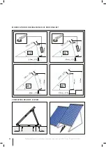
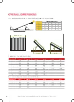
Page 18: ...1 0 del 07 11 2018 SET BASE X 2 X 4 X 4 SET BASE X 2 35 x 25 x 1100 mm FLAT ROOF TRIANGULAR STRUCTURE SYSTEM mm n H mm 35 X 100 Y 100 A 1 B 1 1060 40 X 210 Y 310 A 9 B 13 1200 45 X 310 Y 560 A 13 B 2...

Page 19: ...For distance between anchorage points see page 20 On completion of previous point proceed with instructions on page 23 OPTIONAL MATERIAL Tension wires may be installed to ensure more structural stabil...

Page 20: ...4 R X RAY 15 R X RAY 16 R X RAY 17 R X RAY 18 R X RAY 19 R X RAY 20 R X RAY 21 R SLOPING ROOF FLAT ROOF Each X RAY R manifold must be installed on four fixing points and then use a fixing kit base for...

Page 21: ...R 5 X RAY 10 R 6 X RAY 10 R X RAY 10 10 X RAY 10 R X RAY 13 R X RAY 12 R X RAY 11 R X RAY 10 R X RAY 15 R X RAY 14 R 1921 MAX 1550 MIN 1300 NUM MASSIMO PANNELLI NUM MASSIMO PANNELLI NUM MASSIMO PANNE...

Page 22: ...X RAY 20 R X RAY 19 R X RAY 18 R X RAY 17 R X RAY 16 R NUM MASSIMO PANNELLI NUM MASSIMO PANNELLI NUM MASSIMO PANNELLI NUM MASSIMO PANNELLI NUM MASSIMO PANNELLI NUM MASSIMO PANNELLI 1921 MAX 1550 MIN...

Page 23: ...2 55x20x295 mm ASSEMBLY SEQUENCE PROFILO INFERIORE Once the roof fixing system is installed whatever the type chosen it is necessary to complete the installation with the appropriate parallel profiles...

Page 24: ...2 KIT BASE M8x20 M8x25 M8x75 M8x75 1970 1970 M8x45 M8x25 M8x30 x2 x2 x2 x2 x2 M8x20 M8x25 1970 x1 x1 x1 x1 x1 x1 x1 x1 x2 x2 x4 x2 x4 x2 1 KIT BASE KIT ESTENSIONE KIT BASE TETTO PIANO KIT ESTENSIONE T...

Page 25: ...ASTENING SYSTEM cod 12345678 cod 12345678 M8x20 M8x25 M8x75 M8x75 M8x45 M8x25 M8x30 x2 x2 x2 x2 M8x20 M8x25 x1 x1 x1 x1 x1 x1 x2 x2 x4 x2 x4 x2 1 M8x20 x 300 300 2 1 85 300 300 x 85 M8x20 x 300 300 x...

Page 26: ...26 Technical manual Installation instructions and start up X RAY R ver 1 0 del 07 11 2018 50 10 M8x45 M8x45 7 8 3 4 ASSEMBLY SEQUENCE FOR INSTALLATION OF EXTENSION KIT...

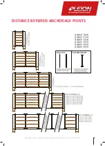
Page 27: ...27 Technical manual Installation instructions and start up X RAY R ver 1 0 del 07 11 2018 VALID FOR BASE KIT EXTENSION KIT COLLECTORS DISTANCE BETWEEN ANCHORAGE POINTS...

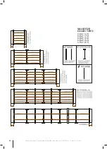
Page 28: ...28 Technical manual Installation instructions and start up X RAY R ver 1 0 del 07 11 2018 VALID FOR COLLECTORS...

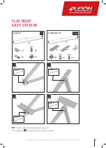
Page 29: ...E KIT BASE TETTO PIANO KIT ESTENSIONE T PIANO 1 2 KIT BASE M8x20 M8x25 M8x75 M8x75 1970 1970 M8x45 M8x25 M8x30 x2 x2 x2 x2 x2 M8x20 M8x25 1970 x1 x1 x1 x1 x1 x1 x1 x1 x2 x2 x4 x2 x4 x2 1 1 1 bis FLAT...

Page 30: ...5 1410mm 510mm 21 272m m 10 119 5mm 30 1040mm 60mm 3 185mm 8 185mm 8 35 60mm 3 1180mm 9 2 0 m m 1 0 7 0 m m 75mm 75mm 40 1290mm 60mm 3 185m m 8 1 1 9 5 m m 45 1410mm 510mm 21 272m m 10 119 5mm 30 1040...

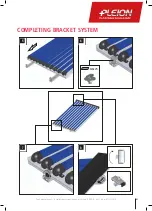
Page 31: ...31 Technical manual Installation instructions and start up X RAY R ver 1 0 del 07 11 2018 M8x25 3 4 5 6 COMPLETING BRACKET SYSTEM 5 7 6 8...

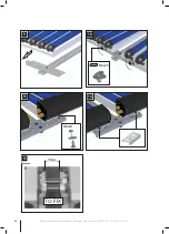
Page 32: ...ions and start up X RAY R ver 1 0 del 07 11 2018 M8x25 M8x30 55mm TO FIX 9 10 10 11 12 M8x25 M8x30 55mm TO FIX 10 10 11 12 M8x25 55mm TO FIX 9 10 10 11 12 13 M8x25 M8x30 55mm TO FIX 10 10 11 12 12 10...

Page 33: ...w NB The above is indicative and does not have the validity of a project The weight of the ballast must be calculated correctly by a studied project qualified structural engineer and the exact weight...

Page 34: ...P E R T U T T E L E T A G L I E 1 9 2 1 3 0 B 30 UGUALE PER TUTTE LE TAGLIE 1921 NUMERO PANNELLI X RAY 10 R X RAY 11 R X RAY 12 R X RAY 13 R X RAY 14 R X RAY 15 R 1 1106 1216 1326 1436 1546 1656 2 231...

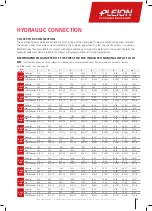
Page 35: ...29 70 Flow 2 10 4 20 6 30 8 40 10 50 12 60 14 70 16 80 18 90 21 00 COPPERDiameter 16 14 18 16 22 20 22 20 28 25 28 25 28 25 28 25 28 25 28 25 X RAY 15 R GrossArea 3 18 6 36 9 54 12 72 15 90 19 08 22 2...

Page 36: ...41 34 44 52 47 70 50 88 54 06 57 24 60 42 63 60 Flow 24 75 27 00 29 25 31 50 33 75 36 00 38 25 40 50 42 75 45 00 COPPERDiameter 35 32 35 32 35 32 35 32 35 32 35 32 35 32 42 39 42 39 42 39 X RAY 16 R G...

Page 37: ...80 200 220 240 260 280 300 320 340 360 380 400 420 440 460 480 500 520 540 Perdite di carico mbar Portata lt h PERDITE DI CARICO DEL SINGOLO COLLETTORE X RAY 10 11 12 13 0 5 10 15 20 25 30 35 40 45 50...

Page 38: ...of number of collectors must be carried out as below NB The cold pipe return must be connected to upper pipe fitting and the hot pipe flow to the lower fitting Temperature probe must be fitted on the...

Page 39: ...the last collector of the series Place the temperature sensor in the sensor pocket on the first collector first on the right Connect the pipes from the boiler room on the left side of the collector se...

Page 40: ...of several probes on the respective collector strings in order to interchange them in the event of a fault and to be able to verify the correct balancing of the circuit in operating conditions For la...

Page 41: ...connection and the hot pipe to the low connection the temperature probe It must be connected to the cockpit on the same side as the connections The inversion of the connections makes it impossible to...

Page 42: ...y hot side to the low fitting On the last string collector connect the 180 curve between the first and the second fitting plug the third lower part Place the temperature probe in the probe holder of t...

Page 43: ...it comprises a protective aluminium profile and a thermal insulating band After installing the collectors assemble the connection kit according to the following steps HYDRAULIC CONNECTIONS INSTALLATIO...

Page 44: ...and or mud force majeure such as fire theft intense cold overheating hurricane lightening earthquake landslide vandalism and other events beyond anyone s control with regard to other parts of the plum...

Page 45: ...on tank the thermal insulation and if present the protective anode of the boiler Resistance of the protection against corrosion Once a year it is necessary to check by means of a pH measuring stick th...

Page 46: ...aws in force Correctly assembled installed and used in accordance with these instructions they do not represent any risk for the safety of persons animals or property The products that fall within the...

Page 47: ...47 Technical manual Installation instructions and start up X RAY R ver 1 0 del 07 11 2018...

Page 48: ...leion Srl si riserva il diritto di apportare modifiche di natura tecnica estetica e commerciale senza alcun obbligo di preavviso Versione 1 1 del 12 05 2014 Cod 1020991200 PLEION Srl Via Venezia 11 CE...

Reviews: